
DLMS Telemetry Interface
May 3 2023 at 12:00 AM
Introduction
DLMS stands for Device Language Message Specification. DLMS/ COSEM (or IEC 62056) is the main global standard for smart energy metering, control and management. It includes specifications for media-specific communication profiles, an object-oriented data model and an application layer protocol. DLMS/ COSEM smart metering protocol is not specific to electricity metering and can also be used for other utilities such as gas, water and heat.
DLMS/ COSEM consists of three main parts:
- COSEM (Companion Specification for Energy Metering): describes the general object model and can be used for all kinds of applications.
- OBIS (Object Identification System): this is the naming system of the objects.
- DLMS (Device Language Message Specification): this is the application layer protocol that is used to transform the data into messages.
Aim
The objective of DLMS is to provide an interoperable environment for structured modeling and meter data exchange. DLMS supports applications such as remote meter reading, remote control, and value-added services for metering any kind of energy, such as electricity, water, gas or heat. DLMS meters supports both pushing and polling services.
Approach
Old DLMS compatible devices mainly make use of DLMS polling to extract data which involves using a ScheduledReceptor devices to connect to the meters, extract the required xml mapping and then making a subsequent request to map the data according to the xml structure. Newer DLMS devices support a more scalable solution called DLMS Push. DLMS Push allows the device to send its data via TCP to a Receptor device configured with a TCP server. DLMS also supports “DLMS Secured” which is Gurux library defined encryption.
Device Functionality Overview
DLMS PUSH
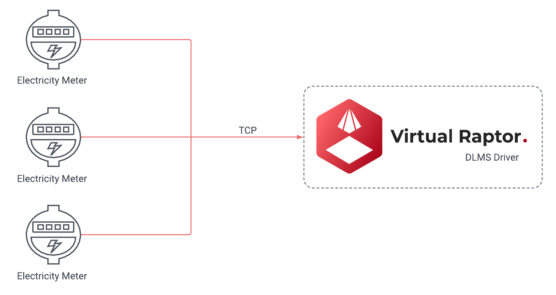
Figure 1 - DLMS PUSH
Capability
- DLMS Push
- DLMS Poll
- Secured DLMS Push
- Secured DLMS Poll
Protocol Information
The DLMS driver is designed to support 2 different device types namely the Scheduled Receptor and Receptor devices. The Scheduled Receptor device is exclusively used for DLMS polling and it is the least scalable of the two different solutions. The Scheduled Receptor device incorporates the use of the Gurux nuget package to set up a client to be able to connect to a DLMS/COSEM device and extract the data by mapping a xml document with the data structure and then afterwards mapping data according to the XML file. The Receptor device spins up a TCP server that waits for TCP packets from the DLMS devices. These devices usually send data on a schedule and the comms can be secured via a DLMS Secured approach. The Secured Approach encrypts the data that is sent by the devices according to the System Title, Authentication Key, Block Cipher key, Security Type and Security Suite.
IP Whitelisting / IP Lookup
This is a check that is used internally on the driver. IP Whitelisting closely ties into your packet tracking. It will do one of two things, if it is set to true, it will request a user from the database and if it is set to false it will use the config credentials. When a user wants to implement the driver in an environment where each device has its own configuration, then IP Lookup should be enabled. However, if all devices have the same configuration, then there is no need to use the IP Lookup feature. The terms IP Whitelisting and IP Lookup are used interchangeably.
| The IP Whitelisting is a security layer that is optional. Ideally, a user can add it in for extra security. If they do not require it, it can be disabled. If the IP Lookup is not used, it will still accept traffic from unverified devices. However that packet that is received will go through a verification process. If it is an invalid DLMS packet, it will just be rejected. |
API Calls
| It is important to add the Add Users to the database with API calls. |
To Add Users/Devices
To add Users/Devices the user can use the following path to use the API: api/Users/Dlms/{DeviceName}/Add.
| The above notation must be used exactly as it is. |
{
    "users": [
        {
            "Ip": "127.0.0.1",
            "Authentication": "HighGmac",
            "Password" : "12345",
            "ConnectionInterfaceType" : "WRAPPER",
            "UseLogicalNameReferencing" : 1,
            "ClientAddress" : -1,
            "ServerAddress" : -1,
            "SecureClient" : 1,
            "BlockCipherKey" : "000102030405060708090A0B0C0D0E0F",
            "SecureClientSecurity" : "AuthenticationEncryption",
            "SystemTitle" : "45444D6B31304D30",
            "AuthenticationKey" : "000102030405060708090A0B0C0D0E0F",
            "SecuritySuite" : "Suite0"
        },
        {
            "Ip": "127.55.6.1",
            "Authentication": "HighGmac",
            "Password" : "12345",
            "ConnectionInterfaceType" : "WRAPPER",
            "UseLogicalNameReferencing" : 1,
            "ClientAddress" : -1,
            "ServerAddress" : -1,
            "SecureClient" : 1,
            "BlockCipherKey" : "000102030405060708090A0B0C0D0E0F",
            "SecureClientSecurity" : "AuthenticationEncryption",
            "SystemTitle" : "45444D6B31304D30",
            "AuthenticationKey" : "000102030405060708090A0B0C0D0E0F",
            "SecuritySuite" : "Suite0"
        }
    ]
}
To Delete Users/Devices
To delete Users/Devices, the user can use the following path to use the API: api/Users/Dlms/{DeviceName}/Delete.
| The above notation must be used exactly as it is. |
{
    "ips": [
        "127.0.0.1",
        "127.55.6.1"
    ]
}
| All API calls require a sufficient API key with a configurator role. It also requires a service ID which is the name of the deploy driver. See Figure 2 |

Figure 2 - Service ID Example
Historic Packet Tracking
Historic Packet Tracking is built into the programming layer where it checks the queue, and if it exceeds a certain number, any record or packet that comes in after that exceeded amount is added to a database and it runs on a schedule. That schedule will batch the records. With a batch number, a user can define how many records they want to get out of the database. The historic record batching size and the historic record interval, are both related to a background process. That process is specifically for that historic packet handling. If the load on the driver in general is too high any incoming packets will fall under historic packets and it will be stored in a database for later processing. That way, there will not be any loss of data if there is a massive load. Therefore it is always retainable.
The historic packets have two essential properties and two optional properties. All of them have their own default values. The user does not have to configure the BackgroundProcessBoundedCapacity and the BackgroundProcessMaxDegreeOfParallelism. There are three properties that are important for the historic packets process, i.e. the HandleHistoricRecordInterval, HistoricRecordBatchingSize and the MaxBoundedPacketMultiplier.
Design Specifications
Scheduled Receptor
Device Configuration Options
"LG_Office": {
  "Enabled": false,
  "ActionDelay": 20000,
  "GroupName": "DLMS",
  "GatewayId": "Lan********",
  "DeviceType": "ScheduledDlms",
  "HostName": "17*.**.***.22",
  "Port": ****,
  "ConnTimeout": 8000,
  "MediaTimeout": 10000,
  "PropertiesDeviceName": "DefaultProperties",
  "Debug": true,
  "ClientAddress": **,
  "ServerAddress": **,
  "Priority": "High",
  "UseLogicalNameReferencing": false,
  "StartProtocol": "Idis",
  "ConnectionInterfaceType": "HDLC",
  "TxMaxFrameSize": 128,
  "RxMaxFrameSize": 128,
  "SecurityLevel": "None",
  "Password": null,
  "Authentication": "None",
  "SecureClient": false
}
| Property | Explanation | Type | Defaults | Options |
| LG_Office | Name of the device to be executed | string | - | - |
| Enabled | Defines whether the device is enabled for execution | bool | - | - |
| DeviceType | Defines the Type of device that has been configured for the driver to execute | string | - | - |
| Debug | Defines whether the device should be executed with debug logs | bool | - | ScheduledDlms |
| GroupName | Group Routing Name | string | - | - |
| HostName | IP/DNS of the device the driver should connect to | string | - | - |
| Port | Port of the device the driver should connect to | int | - | - |
| ConnTimeout | Value in Seconds that dictates when the driver should terminate a connection | int | 10000 | - |
| MediaTimeout | Value in seconds that dictates when the GuruxMedia should terminate a connection | int | 5000 | - |
| PropertiesDeviceName | Defines which propertymaps the driver should use | int | - | DefaultProperties |
| ClientAddress | The Primary Station ID. Client address length is always 8 bits. When authentication level is None, Client address is 16 (0x10). If authentication level is Low, Client address is 17 (0x11) and for High authentication level, Client address is 18 (0x12). The authentication used affects to Client address. If you have a new device, and you do not know anything of it, try using Client address 0x10. Examples of values you can enter: 16, 17, 18 | int | - | - |
| ServerAddress | The Secondary Station ID. Server address consists of two parts, Physical device address and Logical Device Address. Lower HDLC address is reserved for Physical device address and Upper HDLC address is reserved for Logical device address. The idea of this is that because there can be several logical devices inside of one physical device, we can address to each logical device separately. For example, the communication unit of a physical device may be shown as a logical device. | int | - | - |
| Priority | Defines the Priority to be used for connection to Gurux | string | High | Normal, High |
| StartProtocol | Specifying the DLMS protocol type which is utilised for connection. | string | DLMS | DLMS, India, Italy, SaudiArabia, Idis |
| ConnectionInterfaceType | Connection Interface used by DLMS devices. DLMS meters use two different types of PLC interface types. | string | HDLC HDLC, WRAPPER, PDU, WirelessMBus, HdlcWithModeE, Plc, PlcHdlc, LPWAN, WiSun, PlcPrime, WiredMBus, SMS, PrimeDcWrapper | |
| TxMaxFrameSize | Max transfer size for packets from DLMS devices which is dependent on manufacturer. | int | 128 | |
| RxMaxFrameSize | Max Receive size for packets from DLMS devices which is dependent on manufacturer. | int | 128 | - |
| SecurityLevel | Level of Security enforced on connections | string | None | None, Authentication, Encryption, AuthenticationEncryption |
| Password | Password to be used for connection | string | - | - |
| Authentication | Type of Authentication DLMS device utilises for connections | string | None | None, Low, High, HighMd5, HighSha1, HighGmac, HighSha256, HighEcdsa |
| SecureClient | Defines whether the incoming TCP packets should be handled via Secured DLMS | bool | false | - |
| BlockCipherKey | Defines the BlockCipher Key for secured DLMS connection. A 16 octets value that defines the secret encryption key. This information is needed from the meter manufacturer and each manufacturer has its own key | string | - | - |
| System Title | Defines the System Title for secure connection. This is supposed to be set up as an OctetString on the DLMS Device. | string | - | - |
| AuthenticationKey | Defines the Authentication Key for secured DLMS connection. A 16 octet value that is used in AAD(Additional Authentication Data). This information is needed from the meter manufacturer and each manufacturer has its own key. | string | - | - |
| SecuritySuite | The secure level tells how data is secured. In the authentication, the authentication tag is counted for sent data. If data is changed, the authentication tag is not valid and an error occurred. If encryption is used, sent data is encrypted. In DLMS there are three different kinds of ways to secure a connection between the client and the meter. AES-GCM-128 AES-GCM-128 (Suite0); ECDH-ECDSAAES-GCM-128SHA-256 (Suite1); ECDH-ECDSAAES-GCM-256SHA-384 (Suite3) | string | Suite0 | Suite0 , Suite1, Suite2. |
| SecureClientSecurity | Defines whether secure client should be used. | bool | - | - |
PropertyMaps
"DefaultProperties": {
      "DeviceType": "DefaultProperties",
      "GroupName": "DLMS",
      "PropertyMaps": {
        "P3PF": {
          "ObisCode": "1.*.**.*.*.*55",
          "PropertyName": "P3PF",
          "AttributeIndex": 2
        },
        "P2PF": {
          "ObisCode": "1.*.**.*.*.*55",
          "PropertyName": "P2PF"
        },
        "P1PF": {
          "ObisCode": "1.*.**.*.*.*55",
          "PropertyName": "P1PF"
        },
        "TOTALPOWERFACTOR": {
          "ObisCode": "1.*.**.*.*.*55",
          "PropertyName": "TOTALPOWERFACTOR"
        },
        "ACTIVEPOWER": {
          "ObisCode": "1.*.**.*.*.*55",
          "PropertyName": "ACTIVEPOWER"
        },
        "FREQUENCY": {
          "ObisCode": "1.*.**.*.*.*55",
          "PropertyName": "FREQUENCY",
          "TransformSetId": "***0"
        },
        "L0CURRENT": {
          "ObisCode": "1.*.**.*.*.*55",
          "PropertyName": "L0CURRENT"
        },
        "P3CURRENT": {
          "ObisCode": "1.*.**.*.*.*55",
          "PropertyName": "P3CURRENT",
          "TransformSetId": "***0"
        }
      }
    }
| Property | Explanation | Type | Defaults | Options |
| DeviceType | Type of device the instance is created for | string | DefaultProperties for Scheduled Device | – |
| PropertyMaps | Collection of expected properties/obiscodes that are sent by the DLMS device | Collection - Dictionary | – | – |
| ObisCode | Property Identifier for DLMS device | string | – | |
| PropertyName | Name of the Property that will be forwarded to Commander | string | – | |
| AttributeIndex | Data Index you would like to extract from the register | int | – |
Receptor (DlmsPushServer)
Device configuration options
"ServerDevice": {
      "Enabled": true,
      "DeviceType": "DlmsPushServer",
      "Debug": true,

      "GroupName": "PushServer",
      "GatewayId": "something",

      "DeviceGatewayIdProperty": "SerialNumber",
      "EnableIpLookup": true,
      "DeviceAuthorization": false,
      "RegisterAsGateway": false,
      "PropertiesDeviceName": "PushProperties",

      "ClientAddress": -1,
      "ServerAddress": -1,
      "Priority": "High",
      "UseLogicalNameReferencing": true,
      "StartProtocol": "DLMS",
      "ConnectionInterfaceType": "WRAPPER",
      "TxMaxFrameSize": 256,
      "RxMaxFrameSize": 256,
      "SecurityLevel": "None",
      "Password": 12345,
      "Authentication": "HighGmac",
      "SecureClient": true,
      "BlockCipherKey": "0001020304050607000H00002G00003D",
      "SystemTitle": "400000E5B13F0000",
      "AuthenticationKey": "000102030405060708090A0B0C0D0E0F",
      "SecuritySuite": "Suite0",
      "SecureClientSecurity": "AuthenticationEncryption",

      "Address": "Any",
      "Port": 9052,
      "Encryption": "None",
      "DroppedClientDetection": "ReadTimeout,DisconnectOtherConnections",
      "DroppedClientTimeoutSecs": 15,
      "CertificatePath": "/etc/ssl/certs/public.rsa.pfx",
      "CertificatePassword": "",

      "HandleHistoricRecordInterval": 30000,
      "HistoricRecordBatchingSize": 100,

      "ProcessBoundedCapacity": 150,
      "ProcessMaxDegreeOfParallelism": 750,

      "BackgroundProcessBoundedCapacity": 500,
      "BackgroundProcessMaxDegreeOfParallelism": 500,

      "MaxBoundedPacketMultiplier": 4,

      "DropDataLength": 120
    },
| Property | Explanation | Type | Defaults | Options |
| ServerDevice | Name of the device to be executed | string | - | - |
| Enabled | Defines whether the device is enabled for execution | bool | - | - |
| EnableIpLookup | It is used to enable or disable a check that is used internally on the driver | bool | false | - |
| DeviceType | Defines the Type of device that has been configured for the driver to execute | string | - | - |
| Debug | Defines whether the device should be executed with debug logs | bool | - | - |
| GroupName | Group Routing Name | string | - | - |
| RegisterAsGateway | It will either use the meter serial number or the gateway ID defined in the options. | bool | true | - |
| GatewayID | Each and every driver will always have a gateway ID. If the RegisterAsGateway is false and a packet comes in, the packet is decoded and the device options GatewayID is used, and if it is not defined it will use the the collector’s name as GatewayID. However, if the RegisterAsGateway is set to true, it will use the serial number. | string | - | - |
| ClientAddress | The Primary Station ID. Client address length is always 8 bits. When authentication level is None, Client address is 16 (0x10). If authentication level is Low, Client address is 17 (0x11) and for High authentication level, Client address is 18 (0x12). The authentication used affects to Client address. If you have a new device, and you do not know anything of it, try using Client address 0x10. Examples of values you can enter: 16, 17, 18 | int | - | - |
| ServerAddress | The Secondary Station ID. Server address consists of two parts, Physical device address and Logical Device Address. Lower HDLC address is reserved for Physical device address and Upper HDLC address is reserved for Logical device address. The idea of this is that because there can be several logical devices inside of one physical device, we can address to each logical device separately. For example, the communication unit of a physical device may be shown as a logical device. | - | - | - |
| Priority | Defines the Priority to be used for connection to Gurux | string | High | Normal, High |
| UseLogicalNameReferencing | Association Logical Name object is used to tell what kind of functionality (objects and services) meter can offer. It’s also used to tell authentication information (level and password) | bool | - | - |
| StartProtocol | Specifying the DLMS protocol type which is utilised for connection. | string | DLMS | DLMS, India, Italy, SaudiArabia, Idis |
| ConnectionInterfaceType | Connection Interface used by DLMS devices. DLMS meters use two different types of PLC interface types. | string | HDLC | HDLC, WRAPPER, PDU, WirelessMBus, HdlcWithModeE, Plc, PlcHdlc, LPWAN, WiSun, PlcPrime, WiredMBus, SMS, PrimeDcWrapper |
| TxMaxFrameSize | Max transfer size for packets from DLMS devices which is dependent on manufacturer. | int | 128 | |
| RxMaxFrameSize | Max Receive size for packets from DLMS devices which is dependent on manufacturer. | int | 128 | - |
| SecurityLevel | Level of Security enforced on connections | string | None | None, Authentication, Encryption, AuthenticationEncryption |
| Password | Password to be used for connection | string | - | - |
| Authentication | Type of Authentication DLMS device utilises for connections | string | None | None, Low, High, HighMd5, HighSha1, HighGmac, HighSha256, HighEcdsa |
| SecureClient | Defines whether the incoming TCP packets should be handled via Secured DLMS | bool | false | - |
| BlockCipherKey | Defines the BlockCipher Key for secured DLMS connection. A 16 octets value that defines the secret encryption key. This information is needed from the meter manufacturer and each manufacturer has its own key | string | - | - |
| System Title | Defines the System Title for secure connection. This is supposed to be set up as an OctetString on the DLMS Device. | string | - | - |
| AuthenticationKey | Defines the Authentication Key for secured DLMS connection. A 16 octet value that is used in AAD(Additional Authentication Data). This information is needed from the meter manufacturer and each manufacturer has its own key. | string | - | - |
| SecuritySuite | The secure level tells how data is secured. In the authentication, the authentication tag is counted for sent data. If data is changed, the authentication tag is not valid and an error occurred. If encryption is used, sent data is encrypted. In DLMS there are three different kinds of ways to secure a connection between the client and the meter. AES-GCM-128 AES-GCM-128 (Suite0); ECDH-ECDSAAES-GCM-128SHA-256 (Suite1); ECDH-ECDSAAES-GCM-256SHA-384 (Suite3) | string | Suite0 | Suite0 , Suite1, Suite2. |
| SecureClientSecurity | Defines whether secure client should be used. | bool | - | - |
| Address | DNS or IP of the server. Generally this should be left as “Any” due to port forwarding. | string | “Any” | - |
| Port | Port to be used by the server. This should be pointed to by the external routing rules | int | - | - |
| Encryption | Encryption to be used for TCP Server | string | None | None, Tls |
| ValidateClientCertificate | – | bool | false | |
| DroppedClientDetection | The dropped client detection method to use. Multiple values can be specified | string | ReadTimeout,DisconnectOtherConnections | Auto, ReadTimeout, SendPingMessage, DisconnectOtherConnections, NoDataTimeout |
| DroppedClientTimeoutSecs | The timeout, in seconds, after no data is sent or received before dropped client detection method is activated. | int | 120 | 15 - 3600 |
| NoDataTimeout | The number of milliseconds after a connection is established where, if no data is sent or received, the connection is dropped. Set to 0 to disable. | int | 5000 | 500 - 300 000 |
| DropDataLength | Designates the average length of packets. If length is greater, the packet will be discarded | int | 32767 | 10 - 32767 |
| CertificatePath | The path to the certificate file (PFX) to use for encryption. If it is blank, then the ‘CertificateSubjectName’ will be used. | string | - | - |
| CertificatePassword | The password used to unlock the certificate file specified in ‘CertificatePath’ | string | - | - |
| ProcessBoundedCapacity | Max Queue size used for processing incoming packets | int | 500 | - |
| ProcessMaxDegreeOfParallelism | Max amount of packets allowed to be processed in parallel | int | 500 | - |
| DropDataLength | Defines the length of packets that will be dropped when received. This is to prevent pre-emptive spamming attempts with large packets | int | 255 | |
| HandleHistoricRecordInterval | When the queue is full, and packets are posted to the database. This is the timer that is used to run that background process. For example, if the value has been set to 30,000, it will try and execute that process every 30 seconds. So for every 30 seconds it will pull a batch from the database to run in the background while the other processes are busy. It is directly tied to the HistoricRecordBatchingSize. | int | 300 000 | - |
| HistoricRecordBatchingSize | That is the number of records that are retrieved from the database each time the historic background task runs. For example, if it executes the first time, it will try and pull 100 records, and handle those 100 records. And then complete the execution by waiting 30 seconds and it will just continue the process over and over until there is nothing to process in that database. This is to ensure there is no loss of data. | int | 15 | - |
| ProcessBoundedCapacity | This is for live packets. Anything that is received during runtime, and does not fail checks. | int | 500 | - |
| ProcessMaxDegreeOfParallelism | The number of records that will be processed in parallel. | int | 500 | - |
| PacketProcessAbortTimeoutMs | The duration at which a packet will be aborted. If the packet takes too long to be executed, this is the timeout interval for that. | int | 120 000 | - |
| MaxBoundedPacketMultiplier | This is the check used to see if the queue is full. If the packet queue is full, and too many DLMS packets are received, it will take the current queue and multiply it by the number assigned as the MaxBoundedPacketMultiplier value to check if the number of packets have exceeded the amount. If the number of packets in the queue exceeds the amount that is multiplied by MaxBoundedPacketMultiplier value, it will start posting everything to the historic database. That will then be left to the background process to handle those packets as the interval runs. | int | 4 | - |
| BackgroundProcessBoundedCapacity | The size of the queue to handle everything in parallel. This is only used for historic packets. | int | 500 | - |
| BackgroundProcessMaxDegreeOfParallelism | The number of records that will be processed in parallel. This is for a background task. | int | 500 | - |
PropertyMaps
"PushProperties": {
      "DeviceType": "PushDefaultProperties",
      "GroupName": "D********************",
      "PropertyMaps": {
        "TotalPositiveActiveEnergy": {
          "ObisCode": "1.*.**.*.*.*55",
          "PropertyName": "TotalPositiveActiveEnergy",
          "AttributeIndex": 2,
          "DlmsObjectType": "Register",
          "DataIndex": 0,
          "PushProfileSequenceId": *
        },
        "TotalPositiveActivePower": {
          "ObisCode": "1.*.**.*.*.*55",
          "PropertyName": "TotalPositiveActivePower",
          "AttributeIndex": 2,
          "DlmsObjectType": "Register",
          "DataIndex": 0,
          "PushProfileSequenceId": *
        },
        "SerialNumber": {
          "ObisCode": "1.*.**.*.*.*55",
          "PropertyName": "SerialNumber",
          "AttributeIndex": 2,
          "DlmsObjectType": "Data",
          "DataIndex": 0,
          "PushProfileSequenceId": *,
          "DataType": "string"
        }
      }
    }
| Property | Explanation | Type | Defaults | Options |
| DeviceType | Type of device the instance is created for | string | PushDefaultProperties for Receptor Device | – |
| PropertyMapsCollection of expected properties/obiscodes that are sent by the DLMS device | Collection - Dictionary | – | – | |
| ObisCode | Property Identifier for DLMS device | string | – | |
| PropertyName | Name of the Property that will be forwarded to Commander | string | – | |
| AttributeIndex | Data Index you would like to extract from the register | int | – | |
| DlmsObjectType | Designates the Property Type received from the DLMS device | string | – | GXData, GXStructure, GXRegister |
| DataIndex | Designates the data index to be targeted for data extraction. Rarely changes from 0. | int | – | – |
| PushProfileSequence | The order of the pushobjectlist that is used to extract data from a DLMS payload is derived from the property maps. Unfortunately, for accurate data reading, the order of the propertymaps/pushobjectlist should be exactly the same as the received dlms payload structure | int | – | – |
| DataType | DataType to be sent to Commander | string | – | – |
Routing Key Logic
The routing key for these sensors is constructed as follows:
deviceInfo.GatewayId = Options.RegisterAsGateway ? meter.Serial : Options.GatewayId;
deviceInfo.GroupName = meterReading.Measure.ToUpper();
deviceInfo.DeviceType = Options.DeviceType;
deviceInfo.DeviceName = Options.RegisterAsGateway ? DeviceName : meter.Serial;
Meaning you can choose between one of the two configurations for the routing key GatewayID.GroupName:DeviceType|DeviceName
| Options.RegisterAsGateway | Routing key construction: GatewayID.GroupName:|DeviceName |
| True | <meter.Serial>.<meterReading.Measure>:<Options.DeviceType>|<Options.DeviceType> |
| False | <Options.GatewayId>.<meterReading.Measure>:<Options.DeviceType>|<meter.Serial> |
And the available properties are constructed as follows:
CreateProperty("string", nameof(meterReadingData.Id))
CreateProperty("string", nameof(meterReadingData.Serial))
CreateProperty("string", nameof(meterReading.Measure))
CreateProperty("string", nameof(meterReading.Unit))
CreateProperty("string", nameof(meterReading.Direction))
CreateProperty("double", nameof(meterReading.Value))
CreateProperty("DateTime", nameof(meterReading.Date))
Meaning these are the 7 properties to be sent:
| Count | Property Name | Data type | Comment |
| 1 | Id | string | – |
| 2 | Serial | string | – |
| 3 | Measure | string | – |
| 4 | Unit | string | – |
| 5 | Direction | string | – |
| 6 | Value | double | – |
| 7 | Date | DateTime | – |
Usage
Device configuration walkthrough
- We Create a device called: DLMS
- We want the device to run when deployed, so we must make sure that the Enabled tag is set to true.
- Ideally logging should initially be enabled to ensure that everything is running correctly, therefore Debug should be set to true.
- If we want to include anything relating to IP Lookup, we need to set the EnableIPLookup tag to true. If not, then it will not be used.
- If it should be the case that the IP Lookup is not used, we should set the DLMS device options within the configuration. It will include these essential properties, ClientAddress, ServerAddress, Priority, UseLogicalNameReferencing, StartProtocol, ConnectionInterfaceType, TxMaxFrameSize, RxMaxFrameSize, SecurityLevel, Password, Authentication, SecureClient, BlockCipherKey, SystemTitle, AuthenticationKey, SecuritySuite, and SecureClientSecurity.
- If we want the device to set up authorised users, we can set DeviceAuthorization to true. We can use RegisterAsGateway i.e GatewayID.GroupName:DeviceType|DeviceName.
- Associate a property map with DLMS (a set of properties with the device).
- If we want to customise the historic packet settings, we can set a custom execute interval as well as a custom batching size to pull historic packets from the database.
- With regards to the normal driver flow, we can customise these two properties (ProcessBoundedCapacity, ProcessMaxDegreeOfParallelism) for performance reasons. Determines how many packets can be in the queue as well as how many packets can be handled in parallel. This is a customised way of managing the performance to have a bit more control over the driver, and how much resources it uses. This would also apply to the BackgroundProcessBoundedCapacity, and BackgroundProcessMaxDegreeOfParallelism.
- To be able to receive data we have to configure a TCP server. The TCP server relates to all of these properties: Address, Port, Encryption, DroppedClientDetection, DroppedClientTimeoutSecs, CertficatePath, and CertficatePassword. The most important ones are Address and Port.
Deployment Configuration
Steps on how to deploy and configure the driver
The link below demonstrates the steps to follow when a user deploys and configures a V-Raptor driver:
Deployment Manager Application
How to set up port forwarding
- Go to the Connection Manager to set up some routing for the driver.
- Go to Internal Routing.
- Add an internal rule to the port the driver is configured to initialize the TCP server on. You can call it dlms-tcp-internal.
- After successfully adding the internal rule, go back to the connection manager main page and click on External Routing.
- In the External Routing options, this is where you will set up a port that will be used for external connections to the driver.
- Add the external rule. Within the rule, please make sure to specify your internal rule as a routing point which in this case will be dlms-tcp-internal. You can call the rule dlms-tcp-external.
- Now your driver should be capable of receiving TCP comms from external devices.
External HTTP access
To access the driver externally e.g. metrics, HTTP requests, Swagger etc
- Go to the Connection Manager to set up some routing for the driver
- Go to External Routing
- Use Virtual Hosting
- Follow example below
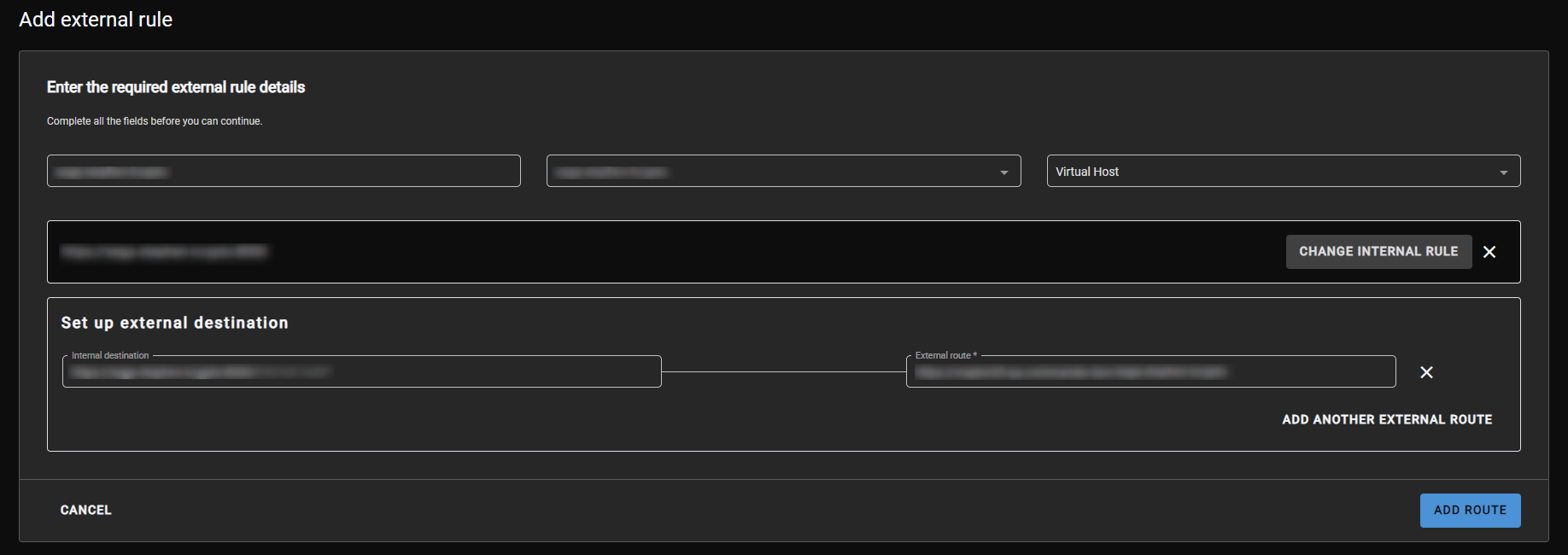
Figure 3 - Add external rule
Release Notes
| Version | Description | Release Date |
| 4.0.43.10 | Push LoopBack + IP whitelisting | 2023-06-28 (QA approval pending) |