
Setup Guide
Jan 6 2023 at 12:00 AM
Overview
The purpose of this document is to outline the steps and details involved in setting up the Micro Raptor for testing purposes.
Before getting started, ensure that plugs are disconnected and do not pull on the wires when unplugging the connectors. In addition, do not touch live, ground or neutral wires, or touch the screws with something that can conduct electricity. Lastly, please disconnect the battery when not in use.
Components
The items needed for the setup are listed below:
- Micro Raptor
- Antenna puck (4G, Wi-Fi and GPS)
- Power supply
- STLINK-V3SET
- Micro-B USB connector cable
- 14-pin STDC14 Cortex Ribbon Cable (cable with matching connectors at each end)
- Micro Sim card
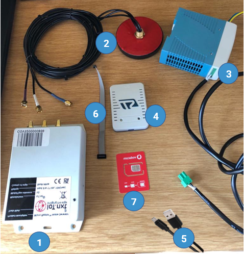
Figure 1 - Micro Raptor Components
Setting up the Mirco Raptor
To setup a Micro Raptor, follow the steps below.
- Open the Micro Raptor casing by removing the screws at the back of the device.
- Unplug the battery to ensure that no power is being supplied to the device.
- Once certain there is no power being supplied, insert the micro SIM card into the SIM slot in the Micro Raptor.To do this properly, unscrew and detach the modem as well as the base board and insert the micro SIM into the slot; ensuring that the SIM is inserted correctly. Once inserted, screw the baseboard and the modem back in.
- Connect the corresponding antenna cables for the antenna puck to the relevant connection point/s on the Micro Raptor as follows:
- The 4G cable connects to the GSM point
- The WIFI cable connects to the WIFI/ BLE point
- The GNSS cable connects to the GPS point
- Reconnect the battery and plug in the power supply connector on the Micro Raptor. A red light will indicate that the Micro Raptor is on.
- Plug the 14-pin STDC14 Cortex Ribbon Cable (cable with matching connectors at each end) into the Micro Raptor and STLINK-V3SET devices, on the available connection points.
Connecting to a laptop/PC
One all the steps above have been completed successfully, The Micro Raptor can be connected to a laptop/PC. To do this, plug the Micro -B connector into the STLINK-V3SET device and the USB connector into your laptop.
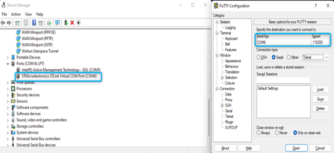
Figure 2 - PuTTY Settings
There are settings that need to be downloaded in order to work with the Micro Raptor. The PuTTY application is used for this.
- Download the PuTTY application via the link: Download PuTTY.
- Install application and run.
- Choose Serial as a connection type within the PuTTY application.
Get the COM port details from the Windows Device Manger and enter this value in the Serial field within PuTTY, and a baud rate of 115200 in the Speed field. To find the serial, right click the window icon and select Device Manager. This will bring up the Device Manger menu. Click on the Port dropdown and there the relevant serial line can be seen. See Figure 2 for more information.
On the PuTTY application, Select ‘Terminal’ and ensure ‘Implicit CR on every LF’ is ticked. This is shown in the figure below.
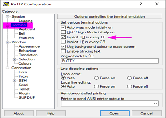
Figure 3 - PuTTY Terminal
- Download the Cube Programmer by following this link: Cube Programmer.
Extract the files from the QA build folder and run the batch file from the latest version (located in this knowledge sharing folder) and run the Setup Device batch file. This is shown in the figure below.
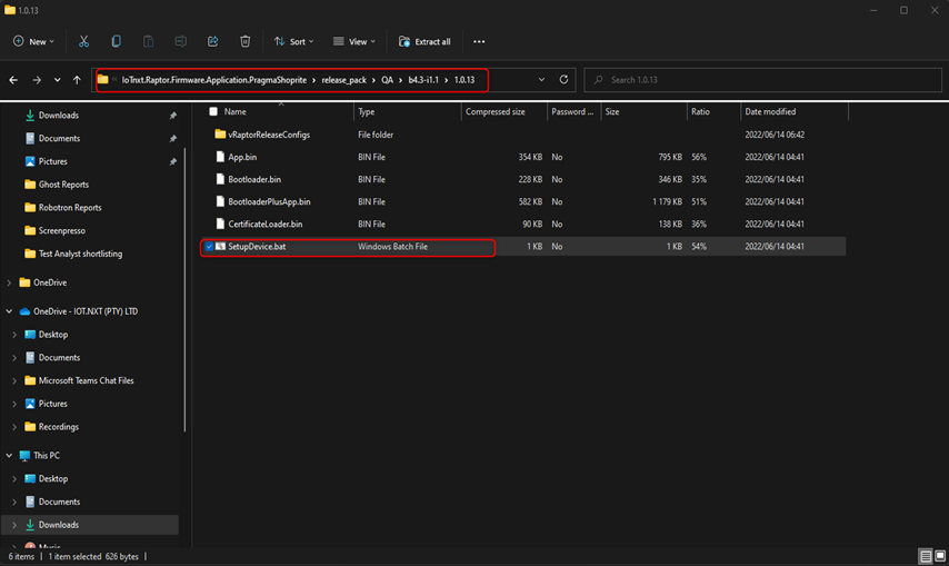
Figure 4 - Setup Device Batch File
DO NOT UNPLUG RAPTOR OR REMOVE THE BATTERY. This could break the Micro Raptor. Ensure that power is on during this process. A mass erase will automatically when the programme is ran. During this process, The Micro Raptor LED will flash Yellow, Blue, Purple then Green. The Green LED will be displayed . once the erase has been done successfully. Contact support should there ever be a red light at any stage. More information on different Micro Raptor LED colours can be found in the Connected Generator section.
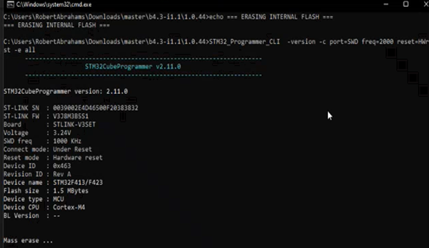
Figure 5 - Mass Erase
- Press Enter or any key to continue and allow programme to boot up. Once it has finished booting up, it will prompt to press any key to exit the console.
- Launch PuTTY to start the debugging session.
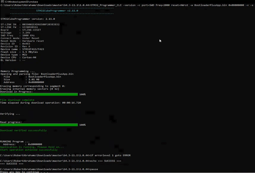
Figure 6 - PuTTY Boot-up
Once these steps are completed successfully, the device has now downloaded a new firmware image, after which it validates the external image within the boot-loader. Where a later version of the image exists within the master branch, the latest version will be installed on the device. Should no issues be found, it then programs the internal flash state and applies the image on the internal flash. Once it has confirmed that the image exists on the internal flash, it removes the image from the external flash. The details on the uplink state whether the connection to the V Raptor is up or not.
To ensure that the Micro Raptor has successfully connected;
- The green light indicates that it is connected to the network.
- The blue light indicates that the device is sending messages to the V Raptor.
- The yellow light indicates that the device is receiving a reply from the V Raptor.
The Gateway ID that needs to be associated in Commander, can be found under the Starting Mobile Generator portion of the PuTTY terminal. Once the Gateway ID has been associated, the values sent by the device can be viewed within the relevant Tenant’s Commander platform.