
Connected Generator
Aug 1 2022 at 12:00 AM
- 1. Overview
- 2. Capabilities of the Connected Generator
- 3. Platform Features
- 4. Micro Raptor v3 Product Information
- 5. Product Accessories
- 6. Device Inspection
- 7. Addendum A: Serial Tool
- 8. Addendum B: Hardware Specifications
1. Overview
1.1. What does the Connected Generator do?
The IoT.nxt® Connected Generator aims to help organisations manage their business continuity in the event that backup power is needed. Vital aspects of a generator such as fuel and coolant level, pressure, temperature, and energy generated are key parameters in determining its health. For the seamless operation of the generator, there needs to be a system to monitor and manage these vital aspects. The Connected Generator solution is engineered to address these concerns and monitor components pertaining to generator health, energy, location, and security.
The IoT.nxt Connected Generator is enabled with Micro Raptor™ architecture providing a range of out-of-the-box features and functionality. The Connected Generator provides telemetry on key properties of a generator such as fuel and coolant level, as well as temperature and energy generated.
The location of the generator system is also tracked using GPS to help locate mobile generator systems and provide a visual system for locating and viewing generator telemetry by location. This telemetry can help to provide seamless operation of the generator by providing a means of early warning and performance monitoring through the Commander Portal.
1.2. What are the benefits of the Connected Generator?
- Tight integration with Commander Portal, which provides a well engineered system for the monitoring of generator health.
- Provides near real-time access to generator performance like energy output, temperature, and fuel and coolant levels.
- Location of connected generators can be tracked.
- Telemetry is secure and transmitted through a multilayer encryption system powered by TLS/DTLS.
- Easy to deploy and integrate with a variety of generator models.
- Over the air (OTA) update capabilities provide a simple way to update devices in the field remotely.
2. Capabilities of the Connected Generator
The Connected Generator will be compatible with fixed and connected generators that have a pre-installed generator controller with active interfaces. Some of the key features include:
2.1. Centralised Monitoring
Enables monitoring of several generators located at multiple sites using a single dedicated dashboard to monitor parameters (generator controller dependant) such as:
- Fuel levels
- Battery levels
- Hours of run time
- Power output
- Location
2.2. Control
Monitoring fuel levels and understanding normal consumption rates, automatically issuing alerts if fuel levels fall below minimum requirements or consumption anomalies are detected.
2.3. Real-time Tracking
The Connected Generator can be located by way of GPS tracking with an adjustable report rate.
2.4. Alerts
Integrate with the generator controllers to set alarm thresholds and receive alerts on anomalies that could affect the use of equipment.
2.5. Remote Management
Remotely access vital information and issue or schedule corrective action from anywhere, anytime.
2.6. Reporting
Gain access to historical reports that offer insight into current and past information relating to operating parameters, alarms and location.
2.7. Fuel Theft Detection
Edge processing and workflows allow for the detection of anomalous refuelling or pilferage events.
2.8. Power and Back-Up Power
In the event that the generator’s main battery fails, the Smart Generator Monitor has a backup battery that can send telemetry for up to 3 days after a mains power loss.
3. Platform Features
The entire IoT.nxt stack has been designed and developed to operate at the Edge, in the Core, or the Cloud. This hybrid platform is designed to suit every operational and business need. Some of the key features include:
3.1. Commander Portal
The IoT.nxt Portal offers application management options such as the configuration of users, groups, roles, granular ad-hoc services, permissions, visualisations and business logic configuration.
3.2. Commander Dashboard
IoT.nxt Commander Dashboard is a real-time operational dashboard that enables a consolidated view of the entire IoT ecosystem, delivering situational awareness and real-time visualisation of all inputs being generated. Commander Dashboard facilitates alarms, bi-directional monitoring and control, as well as visibility and status of equipment or assets.
3.3. Connected Generator Dashboard
Below are some images showcasing the Generator dashboard with diagnostics:
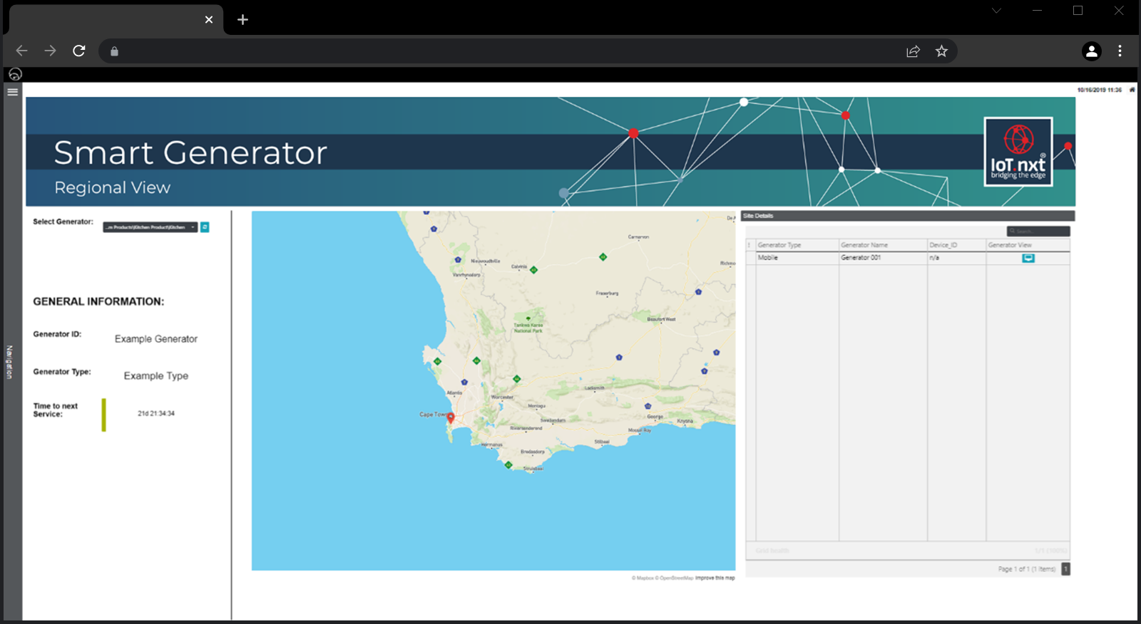 |
Figure 1 - Connected Generator Dashboard, Regional View
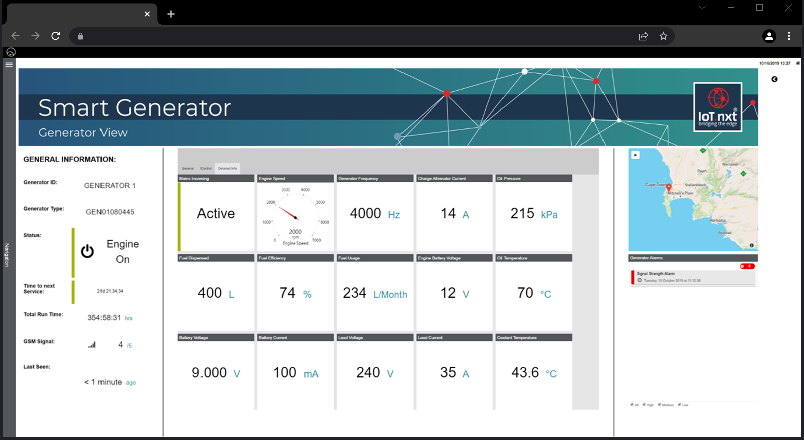 |
Figure 2 - Connected Generator Dashboard, Generator View
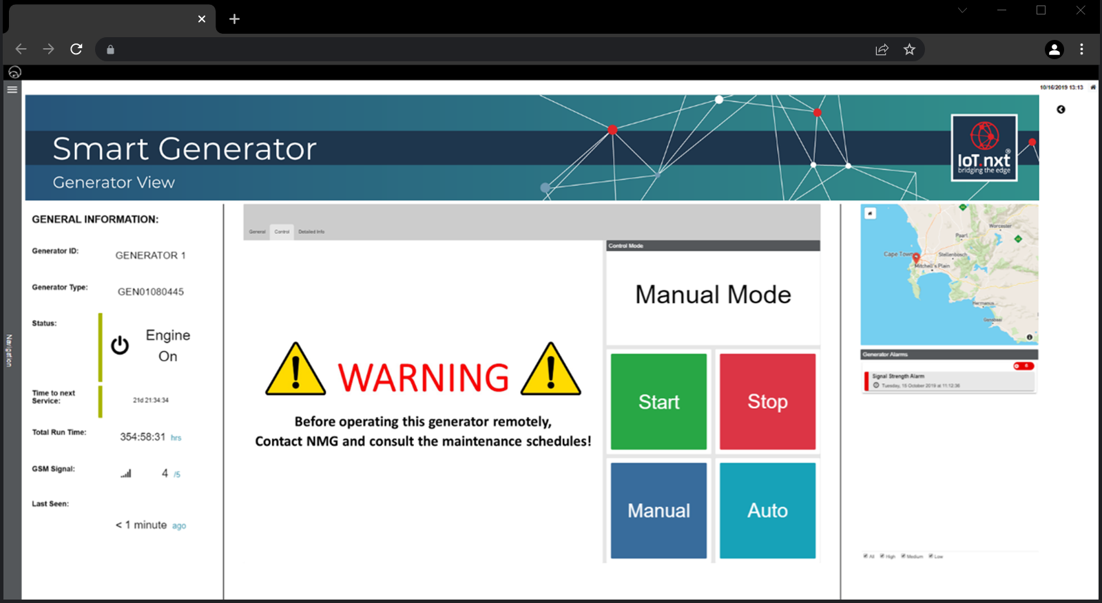 |
Figure 3 - Connected Generator Dashboard, Generator View with an onscreen warning
4. Micro Raptor v3 Product Information
The Micro Raptor V3 product is a compact unit that connects to a generator controller unit which enables it to perform regular monitoring and control actions remotely. The product has the following interfaces:
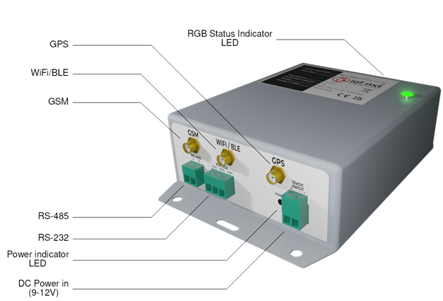 |
Figure 4 - Micro Raptor v3 Product
| This product contains internal batteries. If the device is decommissioned all batteries must be disposed in accordance with local waste regulations. |
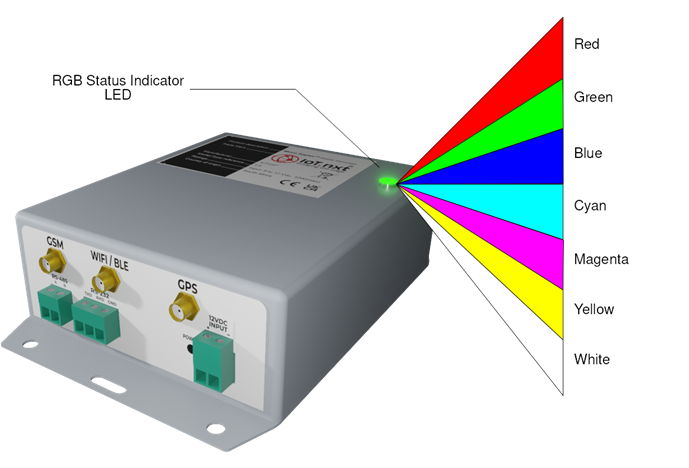 |
Figure 5 - Micro Raptor RGB Indicator
The Mobile Generator product’s dimensions can be seen in Figure 6 below.
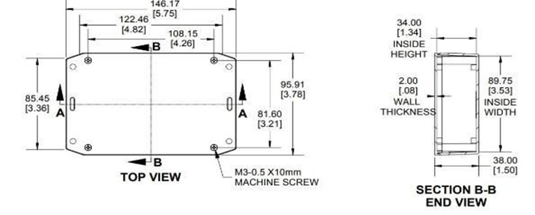 |
Figure 6 - Mobile Generator Product Dimensions
5. Product Accessories
The Mobile Generator product comes with a set of accessories that are required for the installation procedure:
- Combo RF Antenna (4G,WIFI,GPS)
- Set of pluggable connectors
- Power cable
- Communications cable
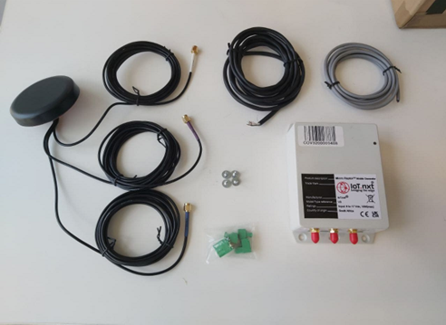 |
Figure 7 - Micro Raptor Accessories 1: Accessory set
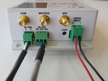 |
Figure 8 - Micro Raptor Accessories 2: Micro Raptor port connections
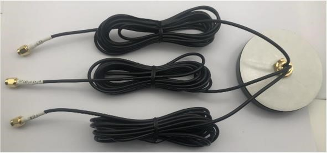 |
Figure 9 - Micro Raptor Accessories 3: Combo RF Antenna
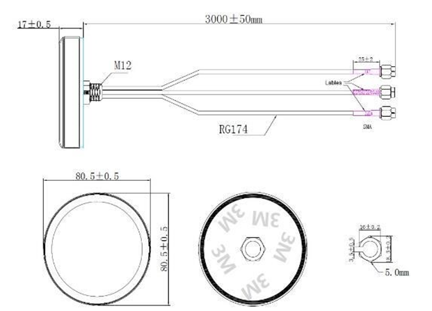 |
Figure 10 - Micro Raptor Accessories 4: Combo RF Antenna diagram
The DB9 female and male connectors from both cables should be connected to provide the USB to 3pin screw terminal connection for the RS-232 interface.
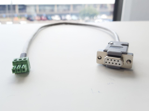 |
Figure 11 - Male DB9 to 3 pin green screw terminal connector
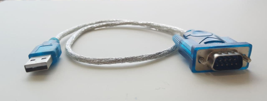 |
Figure 12 - Female DB9 serial to male USB cable
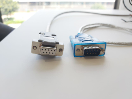 |
Figure 13 - DB9 connectors (side view)
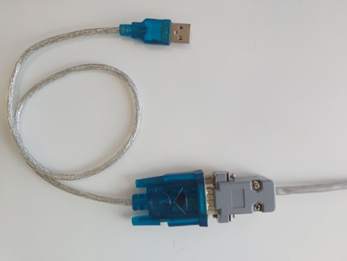 |
Figure 14 - DB9 connectors (top view)
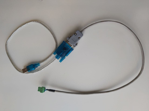 |
Figure 15 - Serial cable connections
6. Device Inspection
After the Mobile Generator product has been installed and wired, there are a few things that need to be inspected and updated where required.
6.1. Power LED
After installation, the first step is to power up the device. If the power is correctly applied, the red power led will be active:
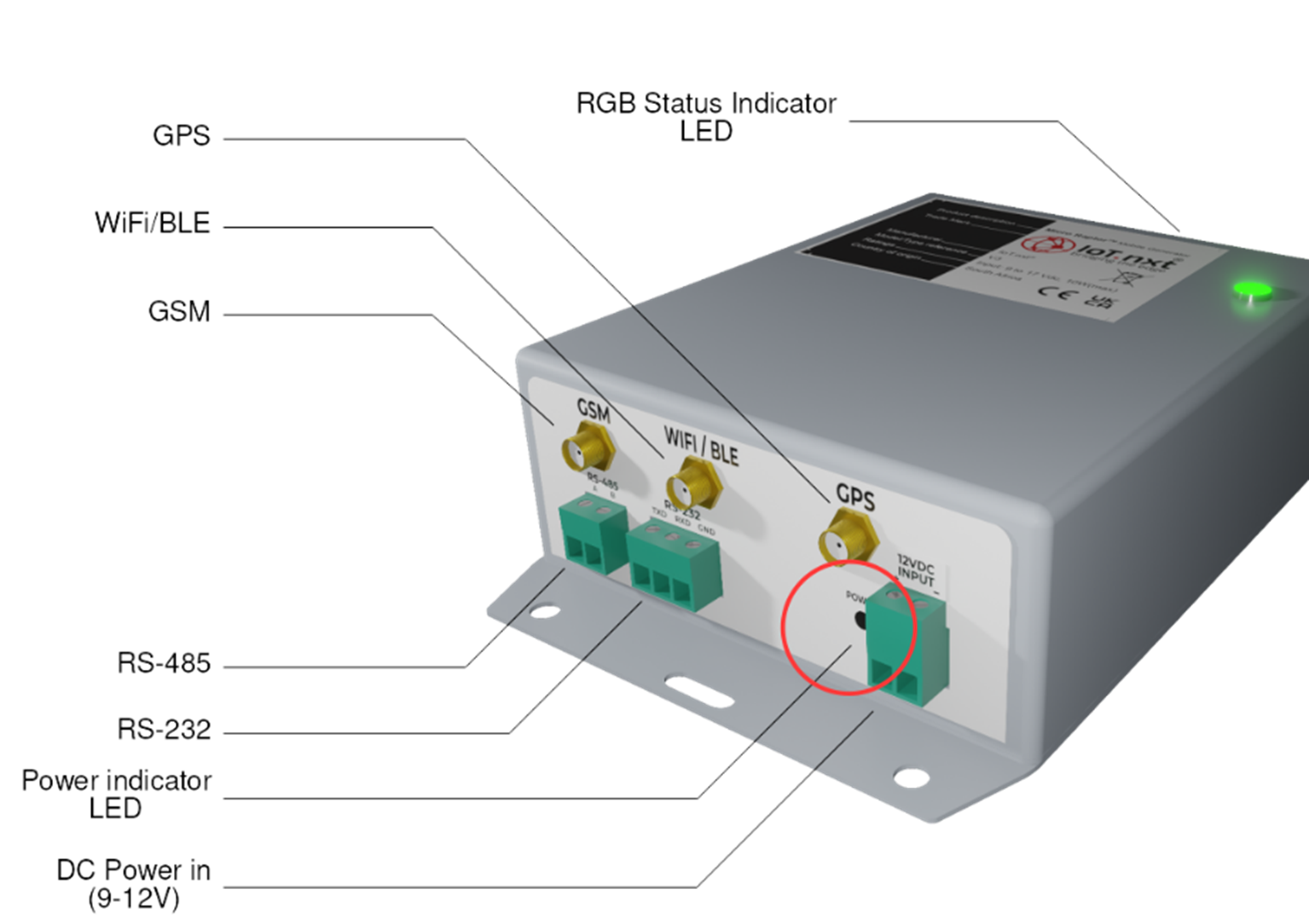 |
Figure 16 - Power LED positioning
6.2. RGB LEDs
Once the power is confirmed on, the RGB LEDs can be observed flashing:
 |
Figure 17 - RGB LED positioning
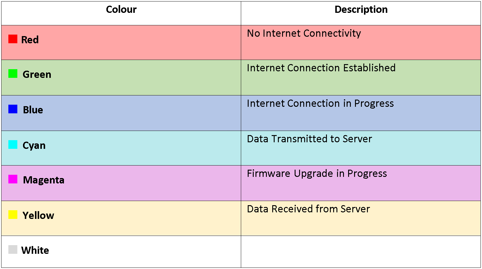
The indicator LED can display 7 different colours at 3 different speeds for a total of 21 possible out-puts. The LED indicates the status of the micro raptor every 2 seconds in an indication event. At eve-ry indication event. The LED will flash quick in 3 configurations.
- 1 fast flash is considered a slow indication
- 2 fast flashes are considered a medium indication
- 3 fast flashes are considered a high indication
note: these flashes will occur within one indication event every 2 seconds. In the case that multiple statuses occur within a single event the colours will flash sequentially in a staggered manner. In general, the sequence will follow the following order.:
- Red (if no internet connectivity is established)
- Blue (while internet connection is taking place)
- Green (once internet connection has been established this will occur at every indication event if internet remains connected)
- Cyan (when data is being transmitted to server)
- Yellow (when data is being received from the server)
- Magenta (if a firmware upgrade is taking place)
These colour outputs and their specific status indications for different flash rates are detailed in the table below.
 |
7. Addendum A: Serial Tool
Note that this serial tool is usually not necessary if the installation was done correctly. Inspecting how the device is operating is with the Micro Raptor Serial Tool. The serial tool involves a software application that should run on a PC/Laptop as well as a RS-232 cable connect-ed between the PC/Laptop and the Mobile Generator device.
|
Figure 18 - RS-232
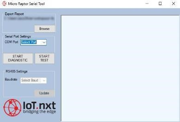 |
Figure 19 - Micro Raptor™ PC application
Connect the cable to the PC and the device and start the application. Choose the relevant COM port of the serial cable (this can be determined by inspecting the windows device manager while connecting the usb serial cable. A new com port should appear. This is the com port that should be selected:
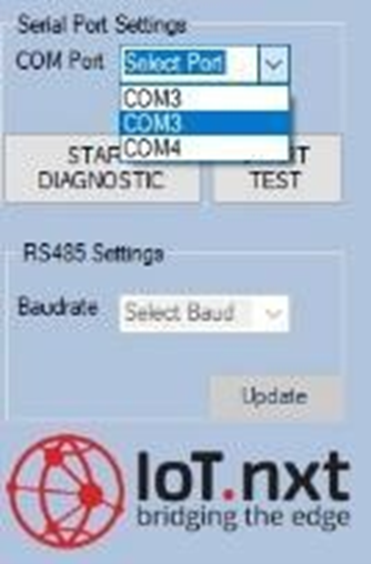 |
Figure 20 - PC application: Select com port
Click on “START DIAGNOSTIC” to inspect the device’s properties:
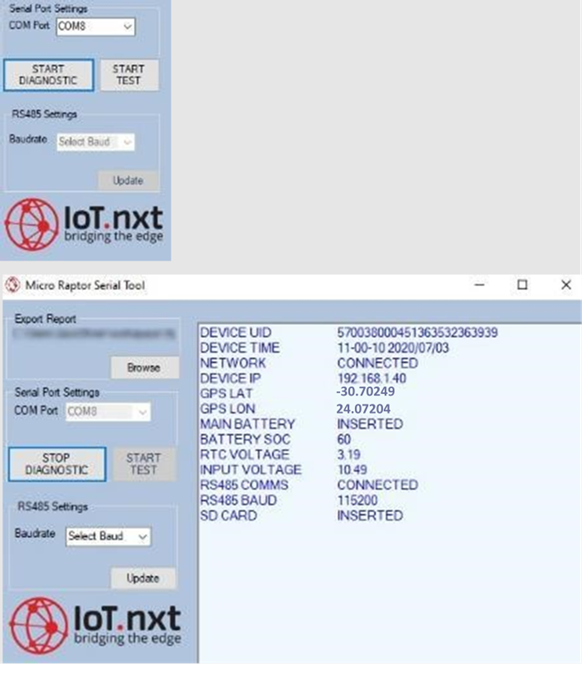 |
Figure 21 - PC application: Start diagnostic
The following properties need to be verified:
- NETWORK
- DEVICE IP
- GPS LAT
- GPS LON
- RS485 COMMS
- RS485 BAUD
7.1. Network/Device IP
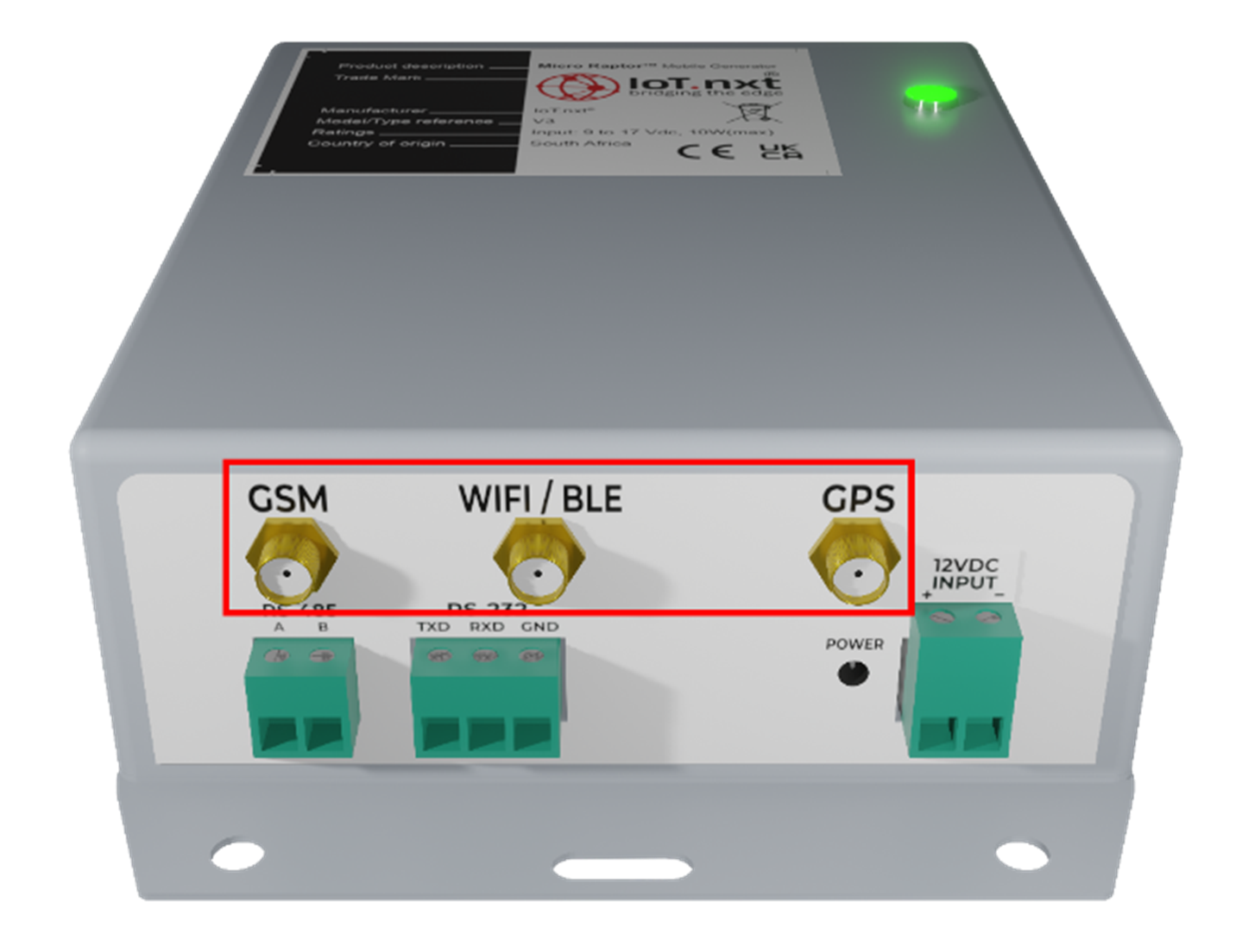 |
Figure 22 - Micro Raptor™ ports
In the case where the network shows “DISCONNECTED” it may mean that the device is busy connecting. If this property does not change to “CONNECTED” within 30 minutes, check the antenna cables to be connected properly and on the correct positions. The device IP will not be displayed in the application if it does not have an active connection.
7.2. GPS LAT/LON
In the case where these values remain 0.00000 for longer than 10 minutes. Verify that the antenna cables are connected properly.
7.3. RS-485 COMMS/BAUD
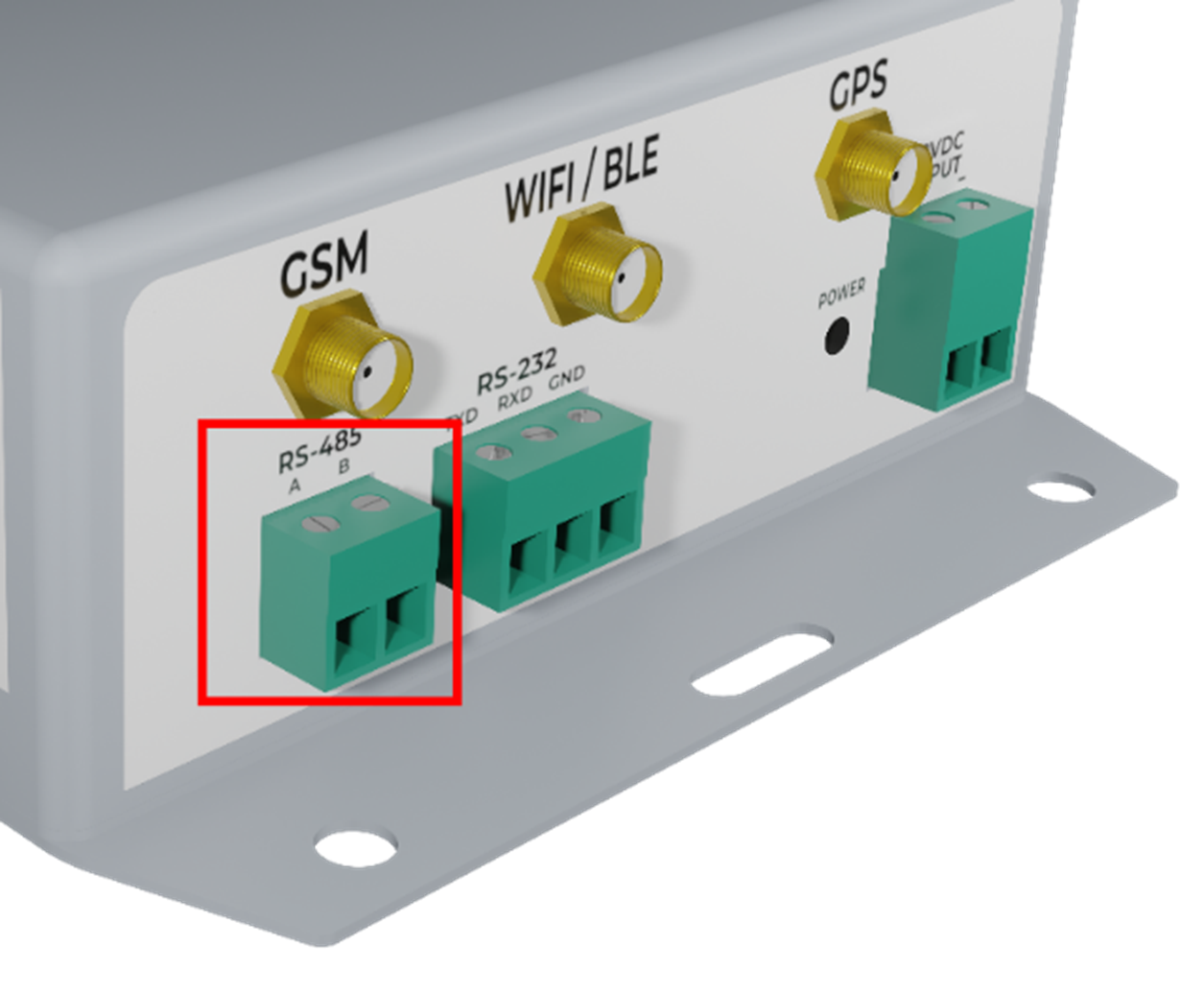 |
Figure 23 - RS-485 Comms Port
It is very important that the RS-485 COMMS always display “CONNECTED”. This means that the Mobile Generator device is communicating with the generator controller. If this shows “DISCONNECTED” try the following:
Power: Verify that the Controller is powered up.
Wiring: Verify that the RS-485 connectors are fitted properly on the controller as well as the Mobile Genera-tor product. Ensure that the pin-out is correct.
Baud rate: Find the Serial menu on the Controller and verify what the RS-485 baud rate setting is set to. Com-pare that setting to the one displayed on the Serial Tool running on the PC. If the two baud rates do not match, use the Serial tool to update the baud rate of the Mobile Generator device:
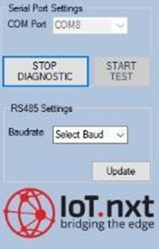 |
Figure 24 - Update Baud rate
While the Serial Tool is running in Diagnostic mode, click on the dropdown list and select the correct baud rate (default 19200) that is displayed on the Generator Controller:
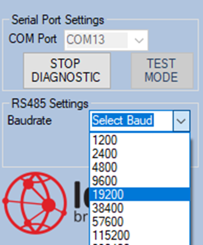 |
Figure 25 - Select correct Baud rate for generator controller
Click on the “UPDATE” button to apply the changes and wait for the data to refresh and display the correct baud rate in the Diagnostic Data Field.
8. Addendum B: Hardware Specifications
Interfaces
Communication
- EIA RS-485 (Half Duplex)
- EIA RS-232 (USART)
User
- RGB Indicator LED
Connectivity
Local Connectivity
- Wi-Fi - IEEE 802.11 b/g/n
- Bluetooth v4.2
Mobile Connectivity
- GPRS/NB-IoT Quad-band 850/900/1800/1900 MHz
- GPRS multi-slot class 12/10
- GPRS mobile station class B
- Compliant to GSM phase 2/2+
- Micro-SIM slot
GPS
- GPS High sensitivity -165dBm @Tracking & -148dBm @Acquisition
- GPS 66 Acquisition Channels & 22 Tracking Channels
- QZSS, DGPS & SBAS (WAAS/EGNOS/MSAS/GAGAN) Support
- Anti-Jamming Multi-tone Active Interference Canceller
Reporting Rate
- Once every 10s to once every day
Remote update
- Firmware over the Air supported
Processor
Processor
- STM32F413ZH Microcontroller
OS
- ARM Mbed OS
Memory
- SD-Card slot (max 64GB)
- 256MB NORFLASH
- 1MB FRAM
Power
Input
- 9V – 17V DC Input supply
Power
- 10W Peak consumption
- 3W Typical consumption
Battery
- Lithium-Ion 3Ah back-up
Security
Hardware
- TRNG (True Random Number Generator)
- TLS Cryptography
- RoT[Root of Trust]
- Secure Boot
Environmental
Temperature
- -10°C to 45°C
Certifications
Certifications
- ICASA Certified
- CE
- UKCA
- RoHS
- REACH
Mechanical
Dimensions
- 147mm x 95mm x 38mm
Material
- ABS
IP Rating
- IP54
Weight
- 256g
Compatibility
The Connected Generator Monitor has been verified with the following generator controllers but is compatible with any standard Generator Controller with an RS-485 Modbus interface (compatibility will be confirmed per request):
Brand and Model
- Deepsea 7320 MKII
- Deepsea 7320 MKI
- Smartgen HGM94XX
- Smartgen HGM61XX
- Smartgen HGM41XX
- IntelliLite AMF25