
User Interface
Jan 31 2023 at 12:00 AM
Description
Edge Raptor runs on a single edge gateway device and supports most standard protocols. It integrates with any sensor or device through our patented SDDI system that expands hardware interfaces of the hosting gateway. This enables the connectivity of solutions where multiple different devices are at the same location.
The Edge Raptor software has all the security and processing capabilities needed at the edge in order to enable rapid deployment. It is intuitive enough to allow 3rd party integration while still maintaining a high level of security, modularity, scalability, and functionality.
The Edge Raptor is intended to be used as an edge gateway where local edge connection with devices is required. It is ideal for industrial or high-end commercial environments where IoT measurement and control of multiple devices or systems are required.
Key Features
- Easily scalable.
- Simple to deploy.
- Easy to update and maintain.
- Secure telemetry.
- Tight integration with Commander.
- Able to abstract data from virtually any device.
- Supports most standard protocols.
- Security and processing capabilities.
- Allows third-party integration.
- Maintains a high level of security, modularity, scalability, and functionality.
What To Expect From This Guide
This guide explains and takes you through the Edge Raptor User Interface. At the end of this guide, you will know:
- The features and user interfaces it provides.
- High-level configuration of the user interface.
- How it links with the rest of the IoT.nxt® technology stack.
Raptor Edge Gateway Portal Landing Page
Figure 1 below displays the landing page for Raptor Edge Gateway Portal. Users can access it using HTTPS on its remote IP address, and if they are locally connected it will have a default local IP address that the user can access if they plug it into their computer. Each user is required to provide a username and password to access the Raptor Edge Gateway Portal home page. The username and password are config specific. Users can be added, and the user can use those credentials to log into the portal. There are default logins for each Raptor, however, when a user builds a config they will need to add a list of users and their access credentials.
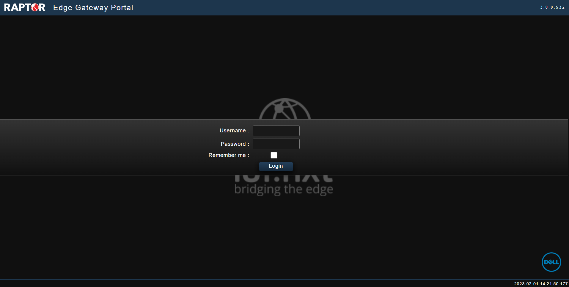
Figure 1 - Edge Raptor Landing Page
Home
When a user logs in, the homepage is displayed (see Figure 2). On the left-hand side, there is a panel of all the management areas of the Edge Raptor User Interface software.
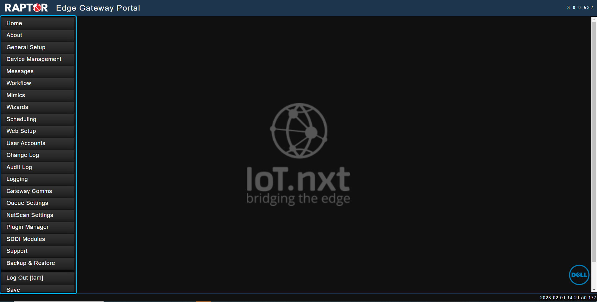
Figure 2 - Home
About
This interface summarizes the main information about the Raptor such as its name, its unique identifier, the version of the snap, its IP address, whether it is sending to the V-Raptor, Commander, an alternate gateway, or an alternate platform. The user is able to see the diagnostics of the hardware, time zones, and startup and up times. When a user selects About on the menu panel Figure 3 is displayed.
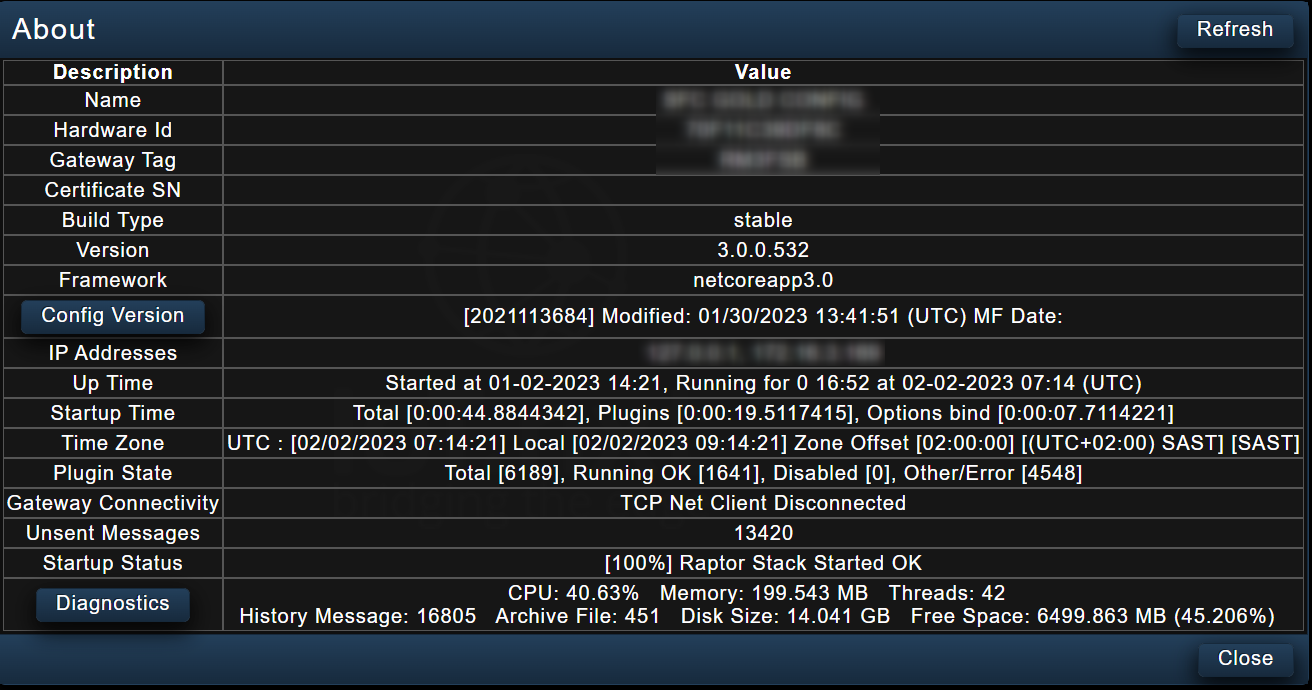
Figure 3 - About
General Setup
The General Setup interface allows the user to set up a specific Raptor. (see Figure 4)
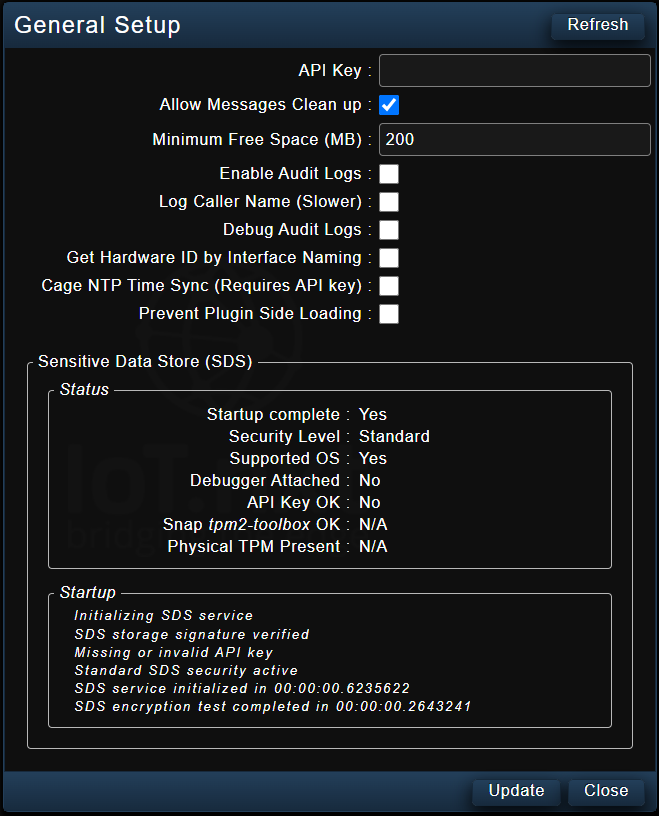
Figure 4 - General Setup
Device Management
Device management is where a user can set up the connection between the Raptor and the devices. When a user selects device management on the menu panel, they are able to see all the different plugins, converters, managers, and tags that are already configured. If the user wishes to create a new one, they will need to select the drop-down list, click the Add button on the top right-hand side of the interface, and the window to configure the new plug-in will open. Otherwise the user has the option to click the edit button of an already existing configured device. The clip below illustrates how to navigate in device management in order to select the type of device a user can create or edit.
Clip 1 - Device Management
| Any plugin or message that is highlighted in red is indicates an issue with the configuration or device. If the line item is greyed out it is either DISABLED from sending information since that device is not connected or configured. If the line item is white, it means that the item is currently enabled to read from a device. |
From the list of integration and configuration items for the devices displayed in the dropdown menu, each one will have its own configuration window. Clip 2 shows the configuration window for the DLMS Plugin where the user can configure items such as the friendly name for the device or for the plugin, its IPs, ports, addresses, protocols, versions, and more.
Clip 2 - Device Management Configuration
Depending on the item being configured, a user can add the translation data point to convert the device’s language to a user-friendly language. Figure 5 shows where a user can create their data points to be read from the devices, and convert the device codes to user-friendly names (OBIS Code - 1.1.32.7.0.255 translated to Friendly Name - VOLTAGEPHASE1 ). Users can also use the device’s scaling on this interface or manually scale the items themselves if they know the scaling offset.
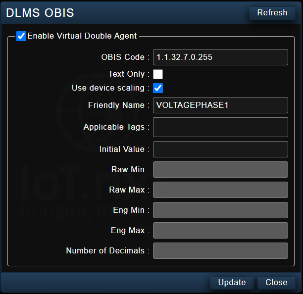
Figure 5 - Device Management Configuration
| An integration specialist can assist in configuring this item. |
Messages
The Messages interface is used to connect the Raptor to an external source, which is Commander. It streams information that has been collected from the devices using device management, and then translates device management into user-friendly terminology to be streamed to platforms such as Commander for data capture and visualization. Within Messages, the user will be able to see a list of already configured messages. If they were to create a new one, they can click the drop-down. Users have the option to select any of the three message types as illustrated in Clip 3 below.
Clip 3 - Messages
There are three types of messages, and these include (see table below);
| Message Type | Description | Use case / Scenario |
|---|---|---|
| Message Subscription | These are write-back messages. If the user requires remote control of a device, this message provides the channel for the communication from Commander to the device via the Raptor (NB: Commander should be configured accordingly in order to process the gateway communication). | In the event of a power failure on site where no technician is available, an on-site generator can be switched on remotely from a Commander Dashboard. |
| Notification Message | These are read messages. This is used to pull telemetry from the device and send the live values to Commander. A notification message creates a group of telemetry messages to be sent to Commander, called a packet. All message properties within the Notification Message will send to Commander based on the trigger specification configured within. | A solution requires 10 connected smart batteries to send data to a dashboard. These messages are required to update the live values every 2 minutes, but also in the event that the current being drawn from any battery is higher than a specified threshold. |
Each message type has a specific purpose, and each one will bring up its own configuration menu where a user can set up a friendly name for that message type, and configure it accordingly. For example, with the Notification Messages, the configuration will entail adding data points (Message Properties) that are required to send within the Notification Message batch for a specified set of rules (Triggers) (see Figure 6).
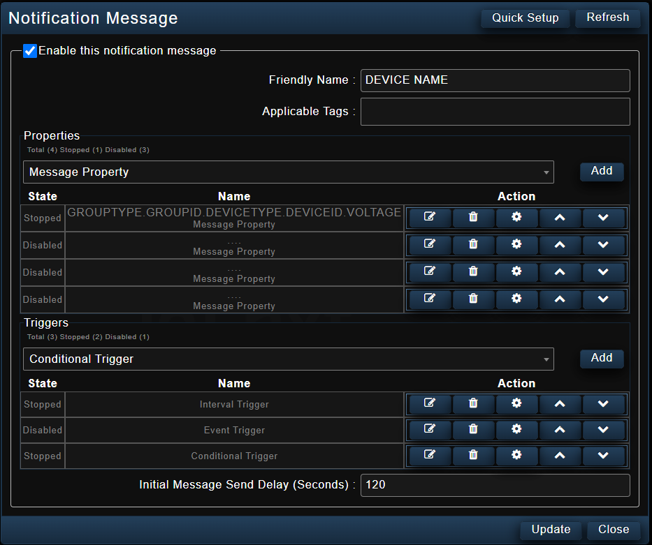
Figure 6 - Notification Messages Configuration
| When naming message properties, it is advised not to use spaces. If in case there is a need to use spaces, resort to using underscores instead. Please refer to Regular Expression (REGEX) documentation for more information on building message strings. |
To set up a message property, users need set up the different key properties for the naming string of the message. The user can select the device and the device property to link to, and that will link them to what they have already set up in device management.
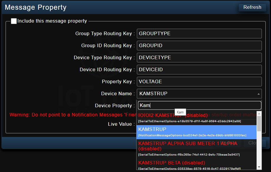
Figure 7 - Message Property
Figure 7 above displays how a user can set up a message property by giving it a group type, group ID, device name, device type, device ID, and the property key of whatever the user is trying to read. This needs to follow a certain structure, and that structure categorizes the message property according to the device being read from. It is important to note that this structure needs to be designed by a solution architect to fit the connection between Raptor and Commander, so that the information on the Commander side can be read and linked accurately. When it comes to selecting the device name and the device property, the interface above is what links to device management. The device name selected is the device the user wishes to connect to, and the device property is what they want to read from the device.
After a user has selected the device that they want to connect to the device name, it will display the device properties that are within the device that has been set up. The live value will display the property the user is currently reading. Whatever device property a user selected, the live value will show them what is currently being read. If no device is connected, this value will not display anything. If it is connected to something, it will display the live value of that device before the interface is closed.
| Remember to select the checkbox at the top left-hand corner that reads INCLUDE THIS MESSAGE PROPERTY. If not selected, it will disable the message until it is needed. The user has the option to go back and select it. |
Figure 8 below shows an example of a configured message property that is reading the battery current from a Delta Orion rectifier on this Raptor with a specific technical architecture structure. This is how the message will then appear in the Raptor.
RAPTOR.TELEMETRY.RECTIFIER.DELTAORION.BATTERYCURRENT.
When it reaches Commander, this is how the message will appear.
<gatewayID>.RAPTOR|TELEMETRY:RECTIFIER|DELTAORION.BATTERYCURRENT.
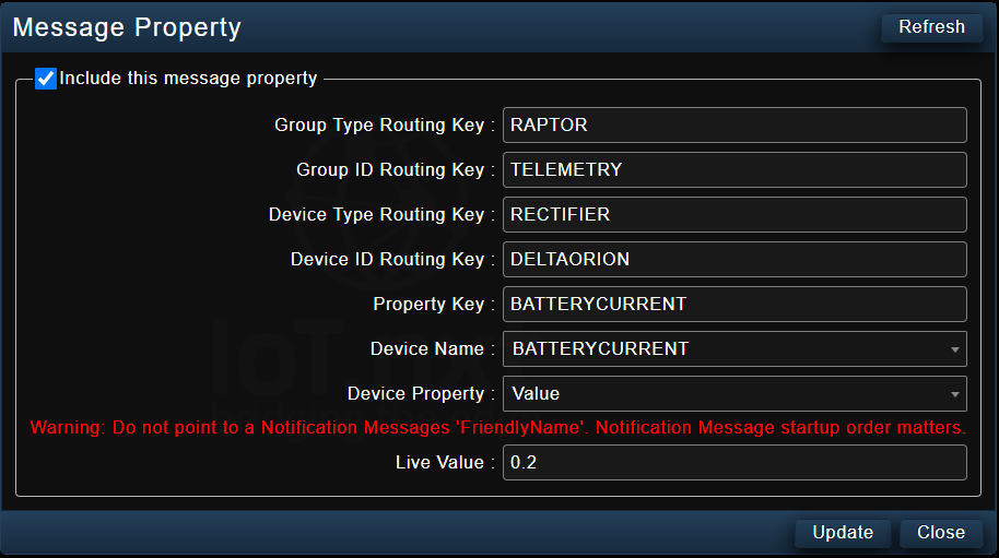
Figure 8 - Message Property
For notification messages, users have the choice of adding message properties (as many as required) and setting the requirements for when the information should send to Commander using the triggers. Users have an option of three different kinds of triggers: Within the notification message users can define the device’s friendly name and then set up the different message property strings to be sent to Commander.
- Interval trigger - this is a time based trigger that will send the message packet at every time interval in seconds.
- Event trigger - will compare two values in the message packet with the following operands (not equal to, equal to, less than, less than or equal to, greater than, greater than or equal to).
- Conditional trigger - this will be an accumulation of events that need to happen, or events and intervals that are required before the packet will be sent. Only once all requirements are met, will the packet send.
The initial Message Send Delay (Seconds) at the bottom of the interface in Figure 6 is very useful especially if the Raptor reboots or if it shuts down and switches back on again. The packet will wait for 120 seconds before it starts sending information, and it will send depending on the trigger. This is to make sure that it does not send sporadic information.
Workflow
Workflow is a way users can create some intelligence and add logic on the Edge Raptor to perform actions based on information being received from the devices and sensors. There is no limit to the number of workflows a user can create. The user can also import workflows from other Raptors if they have the configuration files.
Mimics
This allows the user to set up a set of telemetry they would like to read at a quick glance from devices that are connected. This is useful as the technician on-site does not need to check each device individually, or wait for the Commander portion of the set-up to be complete before being able to see all the devices connected as a whole. Instead, any and all values for a certain configuration to be signed off can be set-up within a Mimic, and the Mimics Gridview opened (see Clip 4) to visualise the live values of all properties configured within the Mimic. A mimic per each device can also be created such as to simply see how the device is performing.
To navigate to the Mimics Gridview screen , users can click on the Gridview button at the bottom right-hand side of the window when editing a Mimic (see Clip 4). The screen displays all the input values and properties configured for that Mimic.
Clip 4 - Mimics Gridview
In a similar way, a user can do a quick setup by clicking the Quick Setup button on the top-right hand side of the Mimic interface. Instead of individually adding the endpoint where the mimic value must be, and then selecting it each time, users can do a quick setup and select all the properties from the device they want.
Wizards
Wizards are used to enable, disable and set up some configurations such as IP and ports for the devices that are on-site based on the golden config that has been loaded on the Raptor. A user can select which wizard they wish to run in order to enable, disable, and configure ports and IP addresses for any of the devices within the configuration.

Figure 9 - Wizards
Within Wizards, a user can either edi existing Wizards, create a new Wizard, import a wizard file(s), export a specific Wizard, or run Wizards. Wizards can be run from within the edit window of a Wizard, or the user can navigate to Wizard View. When a user selects the Wizard View button an interface is displayed as shown in Figure 9, which shows the user what is possible (to enable, disable and configure) within each wizard.
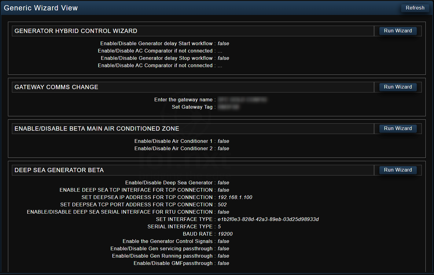
Figure 10 - Generic Wizard View
Above is a generic wizard view which shows users a summary of the current configurations and whether something is enabled or not. If a user would like to change a configuration, or set up a device for the first time, they can click the Run Wizard button next to the specific device. This will take them through each of the different steps to configure IPs, ports and enable or disable certain properties of a device.
Web Setup
When a user selects Web Setup from the menu panel, the interface in Figure 11 is displayed. This is where the user can set up their HTTP and HTTPS ports. They have the option to make changes on the interface and update, or close it.
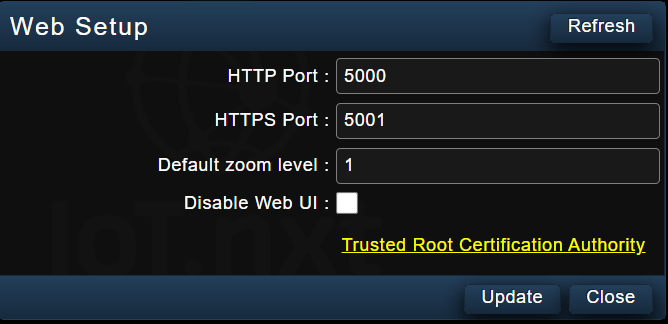
Figure 11 - Web Setup
User Accounts
The User Accounts interface displays all the users that have access and have been associated with this config. It allows a user to add more users. Each user is required to enter a username, set a current password, and confirm the password. They have the option to either update the changes or refresh the screen. When the login information is updated, a user is able to access the Raptor using those credentials.
Change Log
This stores changes that have recently been made and saved on the Raptor, such that a change log file can be created for configuration purposes. It is used to commit changes and track all the additions (i.e adding a device, adding a notification message) that have been made to the configuration. A user has the option to import a change log from another Raptor, export, apply all the change logs and view the change logs that have been applied.
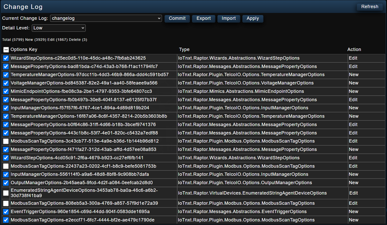
Figure 12 - Change Log
The Change Log window has a Detail Level dropdown menu that a user can use to determine the amount of detail that should be displayed. The detail level can either be Low, Medium or High see Figure 13 below.
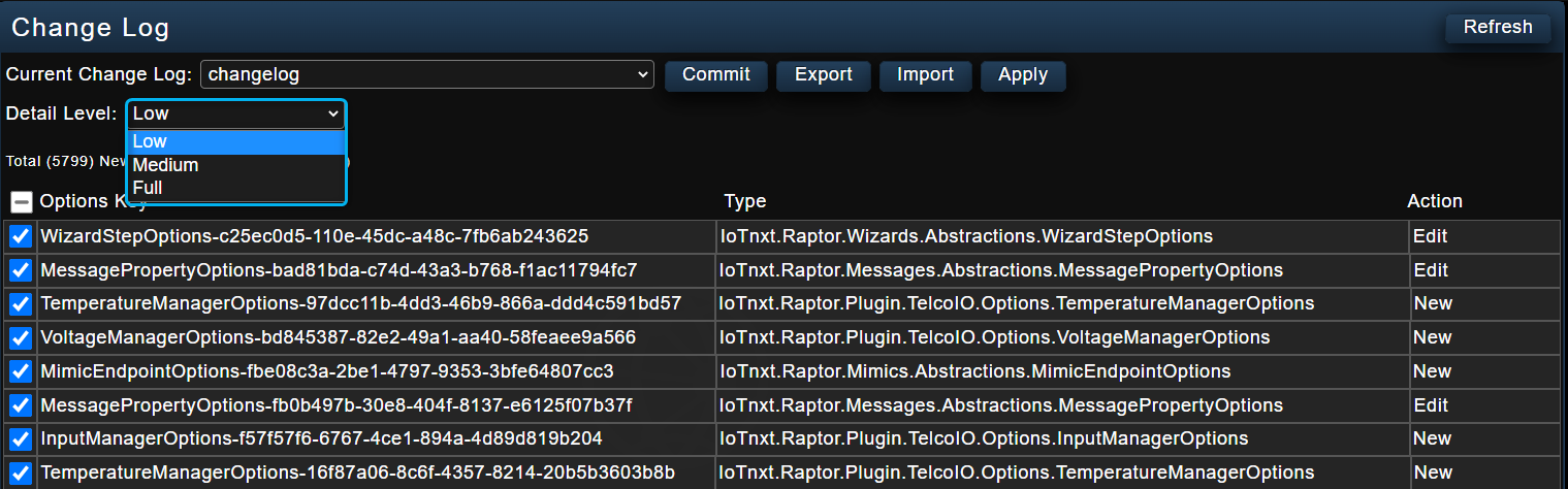
Figure 13 - Detail Level Options
Figure 14 below displays the Change Log if a user selects the detail level option “Medium”. The information displayed shows a low amount of detail in the selected Current Change Log.
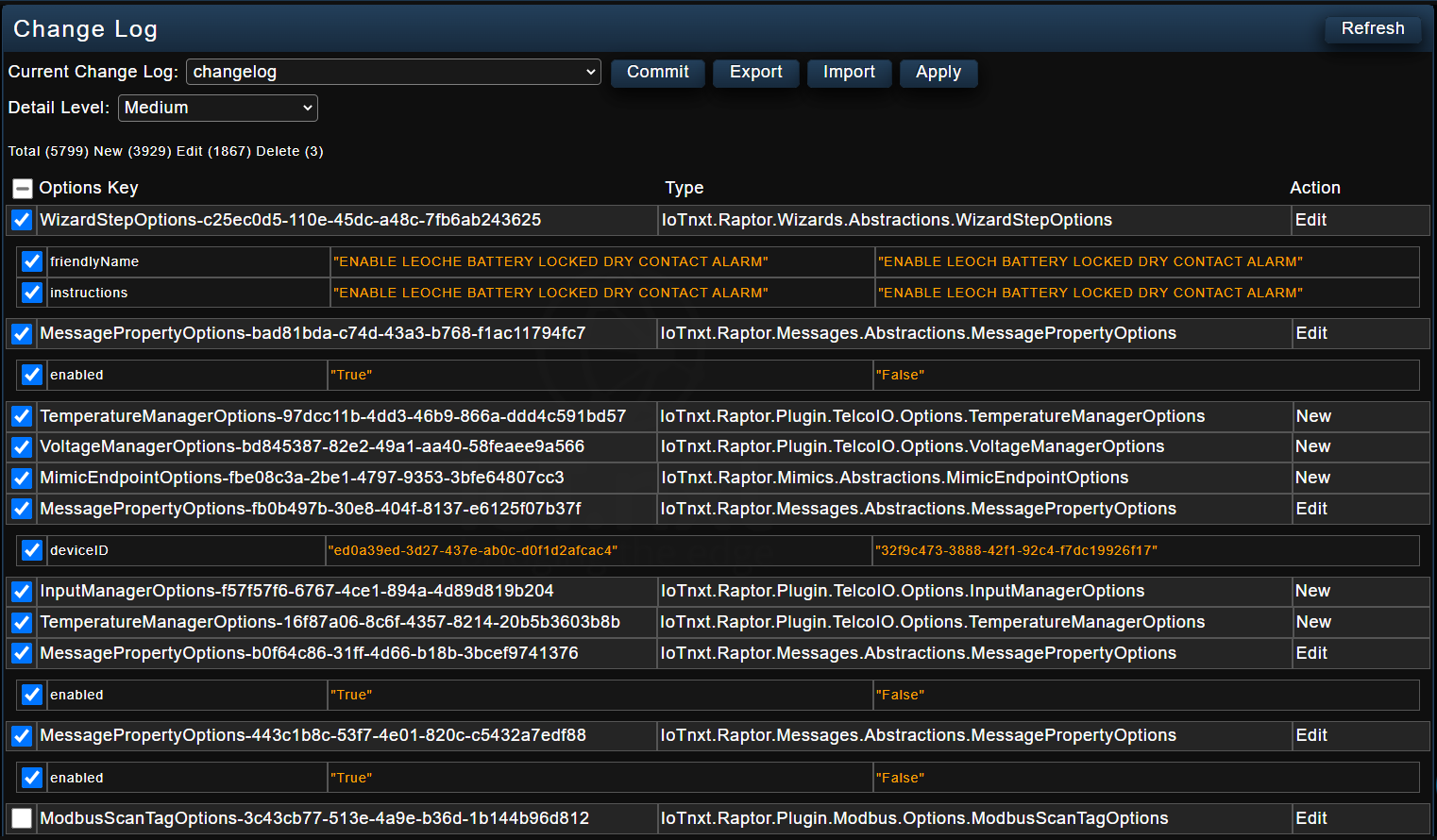
Figure 14 - Medium Detail Level Option
Audit Log
The Audit Log interface gives a user an audit log of what users did, the time period it was done, and where on the Raptor. The user has the option to search using the date, and view the information using the detail level option feature as described in the Change Log interface. When a user selects the Audit Log option in the menu panel, the screen below is displayed (see Figure 15).
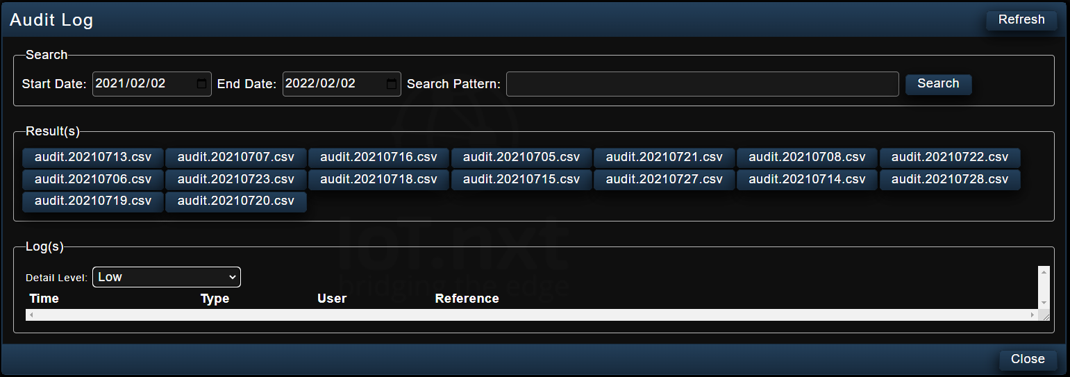
Figure 15 - Audit Log
Logging
This interface gives a user insights into what is happening on the Raptor (in the back-end) and the devices connected to it. It displays live logs of the software’s activities, for instance GPU and CPU updates of the Raptor (see Figure 16).
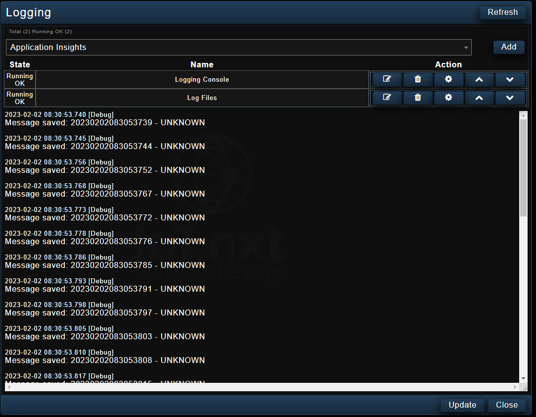
Figure 16 - Logging
Gateway Comms
Gateway Comms allows the user to configure where the Raptor is going to be sending the information to and displays the details. This information is also displayed on the Raptor’s About page. The user can make changes to the name of the “Location Prefix to send to portal”, and this is the name that will appear in V-Raptor (using the TCP net client messaging protocol) and Portal (using the AMQP net client messaging protocol). (see Figure 17)
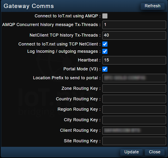
Figure 17 - Gateway Comms
Plugin Manager
Plugin Manager contains all the plugins available in Raptor. Depending on the Raptor version, a user will have different plugins available to them. It allows the user to enable the plugins (by selecting a check box) in order for them to become visible in device management (see Figure 18). When a user opens the Device Management interface, they are able to see all the enabled plugins.
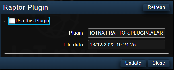
Figure 18 - Plugin Manager
SDDI Modules
The SDDI Modules interface is used in relation to the Telco board that is on the site. A user can setup the default to a particular protocol.
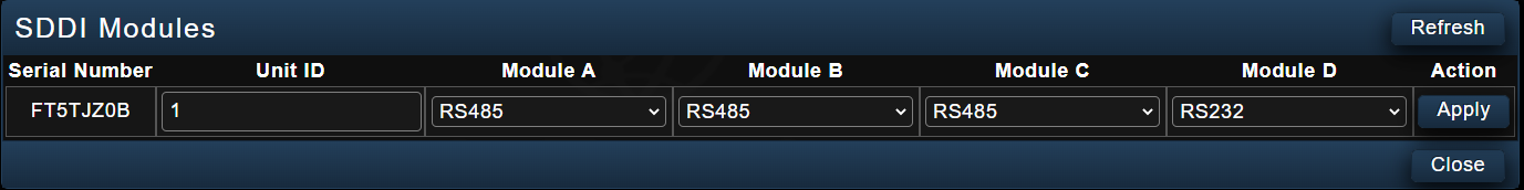
Figure 19 - SDDI
Log Out [your name here]
This interface allows the user to log out of the system.
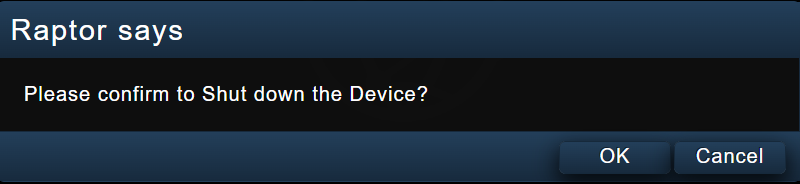
Figure 20 - Log Out [nadia]
Save
This interface gives a user an option to save any changes they would have made on Edge Raptor.
| Remember to save changes being made often. Any changes made that aren’t saved before rebooting the Raptor will be lost! After saving, the Raptor will automatically prompt you to Reboot. |

Figure 21 - Save
Reboot
The Reboot interface allows a user to reboot Edge Raptor. A pop-up message as shown in Figure 22 will be displayed, giving the user an option to either reboot or not.
| Remember to save changes before selecting reboot. Also note that if changes are made that weren’t meant to be made, there is no undo button on the Raptor. Instead, reboot the Raptor without saving and it will restore the configuration to its last saved point. |

Figure 22 - Reboot Pop-up